Input protection – Zilog Z8PE002 User Manual
Page 45
Z8PE002
ZiLOG
Z8Plus OTP Microcontroller
DS008700-Z8X0799
P R E L I M I N A R Y
45
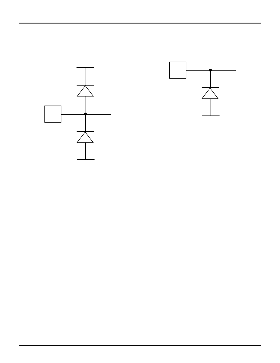
INPUT PROTECTION
All I/O pins feature diode input protection. There is a diode
from the I/O pad to
V
CC
and
V
SS
However, the
PB5
pin features only the input protection di-
ode, from the pad to
V
SS
The high-side input protection diode was removed on this
pin to allow the application of high voltage during the OTP
programming mode.
For better noise immunity in applications that are exposed
to system EMI, a clamping diode to
V
SS
from this pin should
be used to prevent entering the OTP programming mode or
to prevent high voltage from damaging this pin.
Figure 43. I/O Pin Diode Input Protection
PIN
V
CC
V
SS
Figure 44. PB5 Pin Input Protection
PIN
V
SS
PB5
See also other documents in the category Zilog Sensors:
- S3F94C8 (11 pages)
- S3F80QB (29 pages)
- S3F8S19 (38 pages)
- Z51F6412 (96 pages)
- Z51F6412 (54 pages)
- Z51F6412 (55 pages)
- Z16F6411 (216 pages)
- EZ80F93 (11 pages)
- Z16F6411 (20 pages)
- ZMOT0BSB (314 pages)
- ZMOT0BSB (582 pages)
- EZ80F93 (13 pages)
- Z8F083A (14 pages)
- Z8F082A (18 pages)
- Z8F2480 (17 pages)
- Z8F082A (15 pages)
- Z8F0822 (17 pages)
- Z8F6423 (83 pages)
- Z8F2480 (19 pages)
- Z8F2480 (18 pages)
- Z8F6423 (18 pages)
- Z8F6423 (27 pages)
- Z8F6482 (50 pages)
- EZ80L92 (40 pages)
- EZ80L92 (26 pages)
- EZ80L92 (79 pages)
- EZ80F91GA (469 pages)
- EZ80F915 (411 pages)
- EZ80F91NAA (34 pages)
- EZ80F91 (41 pages)
- EZ80L92 (10 pages)
- eZ80F92 (87 pages)
- Z8FMC16 (26 pages)
- Z16FMC6 (41 pages)
- ZUSBOPTS (38 pages)
- ZUSBOPTS (59 pages)
- Z16FMC6 (520 pages)
- Z16FMC6 (8 pages)
- Z16FMC6 (26 pages)
- ZMOT1AHH (25 pages)
- ZMOT0BSB (34 pages)
- EZ80F915 (78 pages)
- EZ80190 (87 pages)
- EZ80L92 (86 pages)
- EZ80F91GA (127 pages)