Timers (continued) – Zilog Z8PE002 User Manual
Page 30
Z8PE002
Z8Plus OTP Microcontroller
ZiLOG
30
P R E L I M I N A R Y
DS008700-Z8X0799
TIMERS (Continued)
A pair of
READ/WRITE
registers is utilized for each 8-bit
timer. One register is defined to contain the auto-initializa-
tion value for the timer. The second register contains the
current value for the timer. When a timer is enabled, the tim-
er decrements the value in its count register and continues
decrementing until it reaches
0
. An interrupt is generated,
and the contents of the auto-initialization register are op-
tionally copied into the count value register. If auto-initial-
ization is not enabled, the timer stops counting when the val-
ue reaches
0
. Control logic clears the appropriate control
register bit to disable the timer. This operation is referred
to as a single-shot. If auto-initialization is enabled, the timer
counts from the initialization value. Software must not at-
tempt to use timer registers for any other function.
User software is allowed to write to any
WRITE
register at
any time; however, care should be taken if timer registers
are updated while the timer is enabled. If software changes
the count value while the timer is in operation, the timer con-
tinues counting from the updated value.
Note: Unpredictable behavior can occur if the value updates at
the same time that the timer reaches
0
.
Similarly, if user software changes the initialization value
register while the timer is active, the next time that the timer
reaches
0
, the timer initializes to the changed value.
Note: Unpredictable behavior can occur if the initialization
value register is changed while the timer is in the process
of being initialized.
The initialization value is determined by the exact timing
of the
WRITE
operation. In all cases, the Z8Plus assigns a
higher priority to the software
WRITE
than to a decrementer
write-back. However, when hardware clears a control reg-
ister bit for a timer that is configured for single-shot oper-
ation, the clearing of the control bit overrides a software
WRITE
. A
READ
of either register can be conducted at any
time, with no effect on the functionality of the timer.
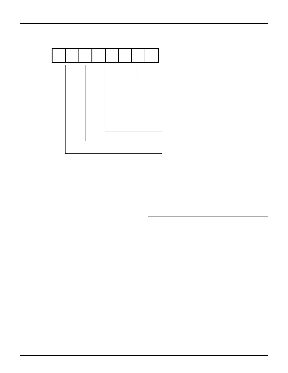
Figure 22. TCTLLO Register
D7
D6
D5
D4
D3
D2
D1
D0
0C0
TCTLLO
TIMER STATUS
D2 D1 D0 T0 T1 T01
----
---- ---- ------------- ------------- ---------------
0 0 0 Disabled Disabled
0 0 1 Enabled Disabled
0 1 0 Disabled Enabled
0 1 1 Enabled Enabled
1 0 0 Enabled*
1
0 1 Enabled* Disabled
1 1 0 Disabled Enabled*
1 1 1 Enabled* Enabled*
N
OTE
:
(*) indicates auto-reload is active.
Reserved (must be 0)
1 = T23 16-Bit Timer Enabled with Auto-Reload Active
0 = T2 and T3 Timers Disabled
Reserved (must be 0)
Note:
Timer T01 is a 16-bit PWM Timer formed by cascading 8-bit timers
T1 (MSB) and T0 (LSB). T23 is a standard 16-bit timer formed
by cascading 8-bit timers T3 (MSB) and T2 (LSB).