Zilog Z8PE002 User Manual
Page 27
Z8PE002
ZiLOG
Z8Plus OTP Microcontroller
DS008700-Z8X0799
P R E L I M I N A R Y
27
In most cases, the
R
D
is 0 Ohms and
R
F
is infinite. These
specifications are determined and specified by the crys-
tal/ceramic resonator manufacturer. The
R
D
can be in-
creased to decrease the amount of drive from the oscillator
output to the crystal. It can also be used as an adjustment
to avoid clipping of the oscillator signal to reduce noise. The
R
F
can be used to improve the start-up of the crystal/ceramic
resonator. The Z8Plus oscillator already locates an internal
shunt resistor in parallel to the crystal/ceramic resonator.
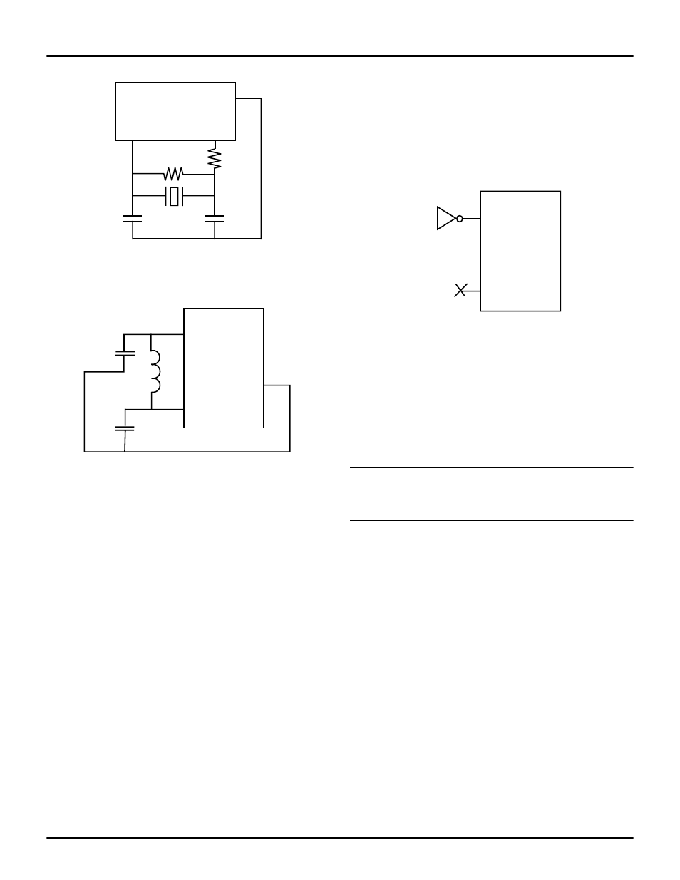
Figure 16, Figure 17, and Figure 18 recommend that the
load capacitor ground trace connect directly to the
V
SS
(GND)
pin of the Z8Plus. This requirement assures that no
system noise is injected into the Z8Plus clock. This trace
should not be shared with any other components except at
the
V
SS
pin of the Z8Plus.
Note: A parallel-resonant crystal or resonator manufacturer
specifies a load capacitor value that is a series combination
of
C
1
and
C
2
, including all parasitics (PCB and holder).
Figure 16. Crystal/Ceramic Resonator Oscillator
Figure 17. LC Clock
XTAL2
Z8Plus
V
SS
XTAL1
C
1
C
2
R
F
R
D
XTAL2
Z8Plus
V
SS
XTAL1
C
1
C
2
L
Figure 18. External Clock
XTAL2
Z8Plus
V
SS
XTAL1
N/C