Lc oscillator, Timers – Zilog Z8PE002 User Manual
Page 28
Z8PE002
Z8Plus OTP Microcontroller
ZiLOG
28
P R E L I M I N A R Y
DS008700-Z8X0799
LC OSCILLATOR
The Z8Plus oscillator can use an inductor capacitor oscil-
lator (
LC
) network to generate an
XTAL
The frequency stays stable over
V
CC
and temperature. The
oscillation frequency is determined by the equation:
where
L
is the total inductance including parasitics, and
C
T
is the total series capacitance including parasitics.
Simple series capacitance is calculated using the equation
at the top of the next column.
A sample calculation of capacitance
C
1
and
C
2
for 5.83-
MHz frequency and inductance value of 27 µH is displayed
as follows:
Thus,
C
1
= 55.2 pF and
C
2
= 55.2 pF.
TIMERS
Two 8-bit timers, timer 0 (
T0)
and timer 1 (
T1
) are available
to function as a pair of independent 8-bit standard timers.
They may also be cascaded to function as a 16-bit Pulse-
Width Modulator (PWM) timer. Two additional 8-bit tim-
ers (
T2
and
T3
) are provided, but they can only operate as
one 16-bit standard timer.
Frequency =
1
2
π (
LC
T
)
1/2
1/ C
T
= 1/C
1
+ 1/C
2
If C
1
= C
2
1/C
T
= 2/C
1
C
1
= 2C
T
5.83 (10^6) =
1
2
π
[27 (10
-6
) C
T
]
1/2
C
T
= 27.6 pF
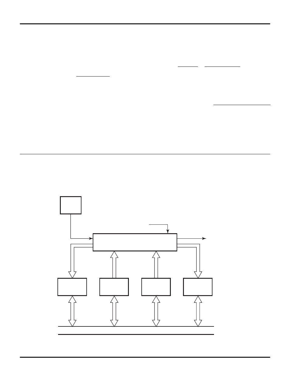
Figure 19. 16-Bit Standard Timer
Enable TCTLL0 (D5)
IRQ5 (T23)
16-bit Down Counter
Internal Data Bus
T2VAL
T3VAL
OSC/8
T3AR
T2AR