Zilog Z8PE002 User Manual
Page 2
Z8PE002
Z8Plus OTP Microcontroller
ZiLOG
2
P R E L I M I N A R Y
DS008700-Z8X0799
GENERAL DESCRIPTION
(Continued)
Both the 8-bit and 16-bit on-chip timers, with several user-
selectable modes, administer real-time tasks such as count-
ing/timing and I/O data communications.
Note:
All signals with an overline are active Low. For exam-
ple, B/
W
, in which WORD is active Low;
and B
/W, in
which BYTE is active Low.
Power connections follow conventional descriptions
below:
Connection
Circuit
Device
Power
V
CC
V
DD
Ground
GND
V
SS
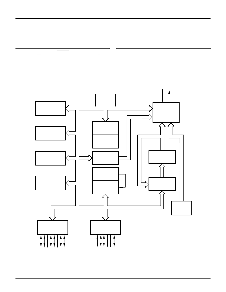
Figure 1. Functional Block Diagram
Two 8-Bit Timers
or One 16-Bit
PWM Timer
One 16-Bit
Standard Timer
Interrupt
Control
One Analog
Comparator
Port A
I/O
ALU
FLAGS
WDT
Register
Pointer
RAM
Register File
Machine
Timing
OTP Program
Memory
Program
Counter
GND
XTAL
Port B
POR &
I/O
V
CC
BO
V
- S3F94C8 (11 pages)
- S3F80QB (29 pages)
- S3F8S19 (38 pages)
- Z51F6412 (96 pages)
- Z51F6412 (54 pages)
- Z51F6412 (55 pages)
- EZ80F93 (11 pages)
- Z16F6411 (20 pages)
- Z16F6411 (216 pages)
- EZ80F93 (13 pages)
- ZMOT0BSB (314 pages)
- ZMOT0BSB (582 pages)
- Z8F083A (14 pages)
- Z8F2480 (17 pages)
- Z8F082A (18 pages)
- Z8F082A (15 pages)
- Z8F0822 (17 pages)
- Z8F6423 (83 pages)
- Z8F2480 (19 pages)
- Z8F2480 (18 pages)
- Z8F6423 (18 pages)
- Z8F6423 (27 pages)
- Z8F6482 (50 pages)
- EZ80F915 (411 pages)
- EZ80F91NAA (34 pages)
- EZ80F91 (41 pages)
- EZ80L92 (40 pages)
- EZ80L92 (26 pages)
- EZ80L92 (79 pages)
- EZ80F91GA (469 pages)
- eZ80F92 (87 pages)
- EZ80L92 (10 pages)
- Z16FMC6 (520 pages)
- Z8FMC16 (26 pages)
- Z16FMC6 (41 pages)
- ZUSBOPTS (38 pages)
- ZUSBOPTS (59 pages)
- Z16FMC6 (8 pages)
- Z16FMC6 (26 pages)
- ZMOT1AHH (25 pages)
- ZMOT0BSB (34 pages)
- EZ80F915 (78 pages)
- EZ80190 (87 pages)
- EZ80L92 (86 pages)
- EZ80F91GA (127 pages)