Dell 3 User Manual
Page 125
PERC 3/DC or PERC 3/DCL Hardware Installation
123
J10 NVRAM Clear
J10 is a 2-pin connector used to clear the memory from the NVRAM, which
stores RAID configuration information. Table 9-4 displays the pinout for
J10.
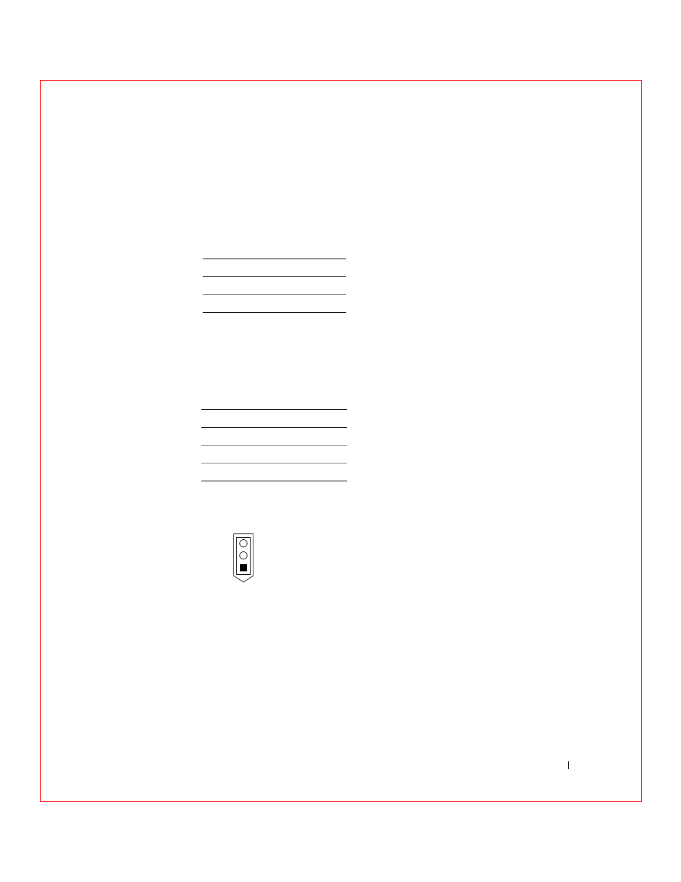
J11 Serial Port
J11 is a 3-pin header that attaches to a serial cable. Table 9-5 and Figure 9-3
display the pinout.
F i g u r e 9 - 3 . J 1 1 S e r i a l P o r t P i n o u t
J13 Dirty Cache LED
J13 is a two-pin connector for an LED mounted on the computer enclosure.
The LED indicates when the data in the cache has yet to be written to the
storage devices. Table 9-6 displays the J13 pinout.
Ta b l e 9 - 4 . J 1 0 N V R A M C l e a r P i n o u t
Pin
Description
1
Signal
2
GND
Ta b l e 9 - 5 . J 1 1 S e r i a l P o r t P i n o u t
Pin
Description
1
Receive data
2
Transmit data
3
Ground
J11
3 Ground
2 Transmit Data
1 Receive Data
- AXIM X3 (158 pages)
- AXIM X3 (366 pages)
- AXIM X3 (178 pages)
- AXIM X3 (2 pages)
- PowerVault MD3220 (32 pages)
- PowerVault MD3220 (76 pages)
- PowerVault MD3220 (11 pages)
- PowerVault MD3220 (76 pages)
- PowerVault MD3220 (272 pages)
- PowerVault MD3220 (32 pages)
- PowerVault MD3220 (2 pages)
- PowerVault MD3220 (74 pages)
- PowerVault MD3220 (28 pages)
- PowerVault MD3220 (32 pages)
- PowerVault MD3220 (32 pages)
- PowerVault MD3220 (237 pages)
- PowerVault MD3220 (32 pages)
- PowerVault MD3220 (32 pages)
- PowerVault MD3220 (388 pages)
- PowerVault MD3220 (32 pages)
- PowerVault MD3220 (6 pages)
- PowerVault MD3220 (174 pages)
- PowerVault 114x (7 pages)
- PowerVault 114x (49 pages)
- POWERVAULT MD3600F (222 pages)
- PowerVault MD3200i (22 pages)
- PowerVault MD3200i (32 pages)
- POWERVAULT MD3600F (2 pages)
- POWERVAULT MD3600F (222 pages)
- PowerVault MD3200i (34 pages)
- POWERVAULT MD3600F (17 pages)
- PowerVault MD3200i (32 pages)
- POWERVAULT MD3600F (90 pages)
- POWERVAULT MD3620F (16 pages)
- POWERVAULT MD3600F (38 pages)
- POWERVAULT MD3600F (318 pages)
- PowerVault MD3200i (32 pages)
- PowerVault MD3200i (75 pages)
- PowerVault MD3200i (32 pages)
- PowerVault MD3200i (32 pages)
- POWERVAULT MD3600F (90 pages)
- PowerVault MD3200i (21 pages)
- PowerVault MD3200i (32 pages)
- PowerVault MD3200i (32 pages)
- POWERVAULT MD3600F (2 pages)