Perc 3/sc card layout, Installation steps – Dell 3 User Manual
Page 105
PERC 3/SC Hardware Installation
103
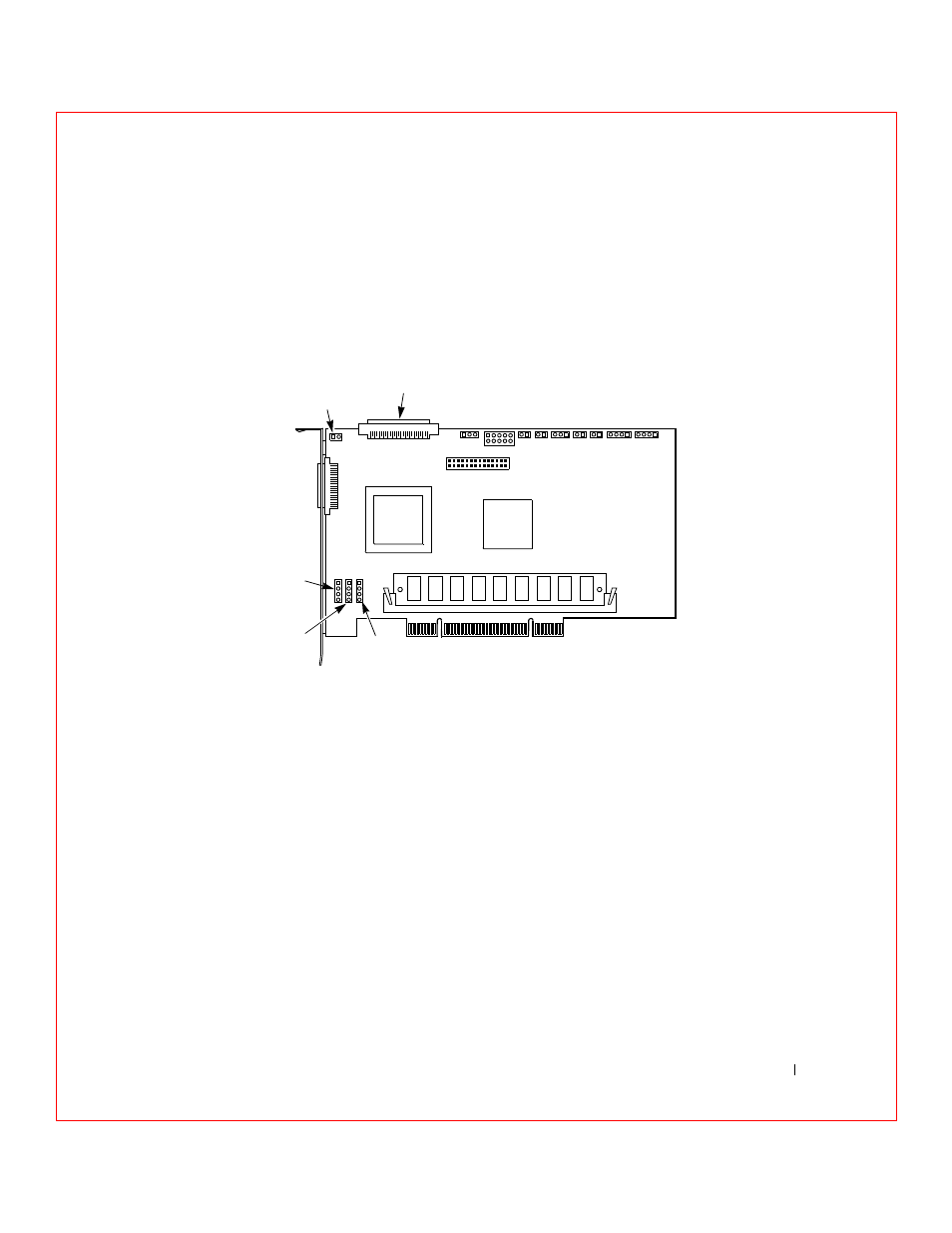
PERC 3/SC Card Layout
Figure 8-1 shows the PERC 3/SC card, jumpers, and connectors.
F i g u r e 8 - 1 . P E R C 3 / S C C a r d L a y o u t
Installation Steps
This section provides an overview of installing the RAID controller. See the
following sections for more information about each step.
1
Unpack the PERC 3/SC controller and inspect for damage.
Make sure all items are in the package. If damaged, call your Dell™
original equipment manufacturer (OEM) support representative.
2
Turn the computer off and remove the cover.
3
Check the jumper settings on the PERC 3/SC controller.
4
Set SCSI termination.
5
Install the PERC 3/SC card.
J12
Non-Buffered 3.3V DIMM Socket
J17
J15
J16
RUBI Slot
Interrupt Steering
J15
RUBI Slot
Interrupt Steering
J16
RUBI Slot
Interrupt Steering
J17
External
SCSI Connector
J13
SCSI Bus
Termination Power
J10
Internal
Straddle Mount
Connector for
Battery Backup Unit
J1
J2
J3 J4 J5
J6 J7
J8
J9
J1 SCSI Bus Termination
Enable Control
J2 CPLD
Programming
J8 User Activity
LED
J4 Serial EPROM
J5 Serial Port
J6 Write Pending
J3 NVRAM Clear
J7 Bios Enable
J9 I2C
Connector
J14
J11