6 onboard headers and connectors – NEXCOM NEX 611 User Manual
Page 22
Copyright © 2011 NEXCOM International Co., Ltd. All Rights Reserved.
11
Chapter 2: Installation
NEX 611 User Manual
2.6 Onboard Headers and Connectors
Onboard headers and connectors are NOT jumpers. Do NOT
place jumper caps over these headers and connectors. Placing
jumper caps over the headers and connectors will cause
permanent damage to the motherboard!
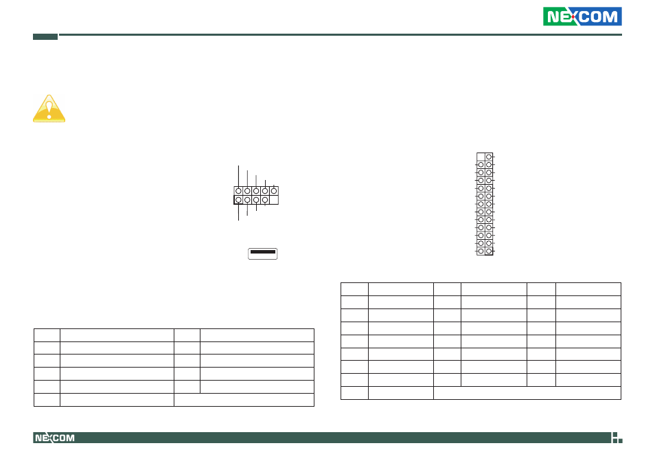
USB 2.0 Headers
USB 2.0 Headers
(9-pin USB6_7) (see p.10, No. 29)
(9-pin USB8_9) (see p.10, No. 30)
(9-pin USB10_11) (see p.10, No. 31)
(USB12) (see p.10, No. 33)
Besides six default USB 2.0 ports on the I/O panel, there are three USB 2.0
headers and one USB port on this motherboard. Each USB 2.0 header can
support two USB 2.0 ports.
DUMMY
GND
GND
+B
-B
USB_PWR
+A
-A
USB_PWR
1
Pin
Signal Name
Pin
Signal Name
1
USB_PWR
2
-A
3
+A
4
GND
6
USB_PWR
7
-B
8
+B
9
GND
10
DUMMY
Print Port Header
(25-pin LPT1)
(see p.10, No.12)
1
SPD0
STB#
SPD1
SPD2
SPD3
SPD4
SPD6
SPD7
GND
GND
SLIN#
PINIT#
ERROR#
AFD#
GND
GND
GND
GND
GND
GND
SPD5
ACK#
BUSY
PE
SLCT
Pin
Signal Name
Pin
Signal Name
Pin
Signal Name
1
STB#
2
SPD0
3
SPD1
4
SPD2
5
SPD3
6
SPD4
7
SPD5
8
SPD6
9
SPD7
10
ACK#
11
BUSY
12
PE
13
SLCT
14
AFD#
15
ERROR#
16
PINIT#
17
SLIN#
18
GND
21
GND
22
GND
24
GND
25
GND