Appendix b: connector pinouts, Audio connector pinout diagram – Dan Dugan Sound Design E-2 User Manual
Page 61
Dugan Model E-2 User Guide
61
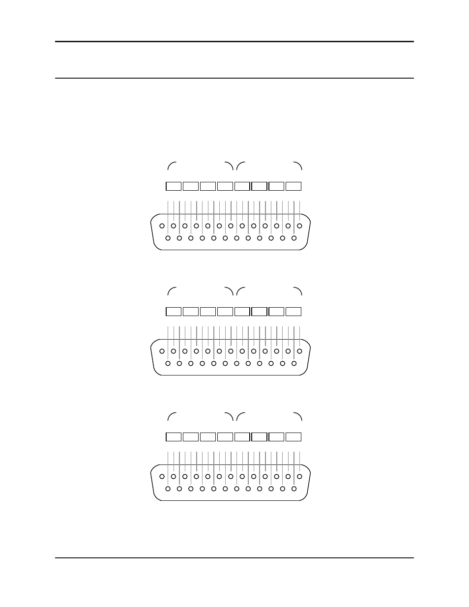
Appendix B: Connector Pinouts
These DB25 connectors are wired with the TASCAM digital standard but are used for
analog signals.
Figure B-1
Audio connector pinout diagram
AUDIO I/O 5-8
XLR Squid Labels
1/2
3/4
5/6
7/8
1/2
3/4
5/6
7/8
G C H G C H G C H G C H G C H G C H G C H G C H
13
25
14
1
5
6
7
8
5
6
7
8
Analog In
Analog Out
AUDIO I/O 1-4
XLR Squid Labels
1/2
3/4
5/6
7/8
1/2
3/4
5/6
7/8
G C H G C H G C H G C H G C H G C H G C H G C H
13
25
14
1
1
2
3
4
1
2
3
4
Analog In
Analog Out
AUDIO I/O 9-12
XLR Squid Labels
1/2
3/4
5/6
7/8
1/2
3/4
5/6
7/8
G C H G C H G C H G C H G C H G C H G C H G C H
13
25
14
1
9
10
11 12
9
10
11 12
Analog In
Analog Out
Music System Threshold signals for groups a, b & c are input to channels 9, 10 & 11
This manual is related to the following products: