4 arrayprocessing dialog – d&b TI 385 d&b Line array design User Manual
Page 51
ArrayProcessing sets the target frequency response of the
applied system to its original reference response. The
optional CUT mode functions as usual: the low frequency
level is reduced. The source is now configured for use with
the system's dedicated subwoofers.
The CPL functionality is still available with ArrayProcessing
being active. However, its traditional functionality of
compensating for array length and curvature has been
taken over by ArrayProcessing as it provides a uniform
target frequency response for every array. With
ArrayProcessing, CPL now provides an additional user
parameter to adjust the system's tonal balance, for example
to cater for the venue acoustics or individual taste. Its
characteristics are identical for all ArrayProcessing line
arrays. All ArrayProcessing line arrays used in a system
should be set to the same CPL value.
11.4 ArrayProcessing dialog
To access the above mentioned user parameters of
ArrayProcessing, open the ArrayProcessing dialog by
clicking the Process button in the ArrayProcessing section of
the respective array.
The ArrayProcessing dialog is subdivided into two sections.
On the left hand side, the ArrayProcessing (AP) slots can be
selected for editing and saving user parameters and
resulting ArrayProcessing data. This includes a name and
comment which will later be visible in R1. For each slot, a
Clear button (CLR) is provided which allows you to clear all
data stored to that particular slot. Note that the Clear
button is only available when the respective slot contains
data.
The other section on the right hand side includes two tabs,
Direct sound level vs. distance/dB and Result.
On the Direct sound level vs. distance/dB tab, you can
define the target level distribution for the ArrayProcessing
calculation. The following user parameters are available:
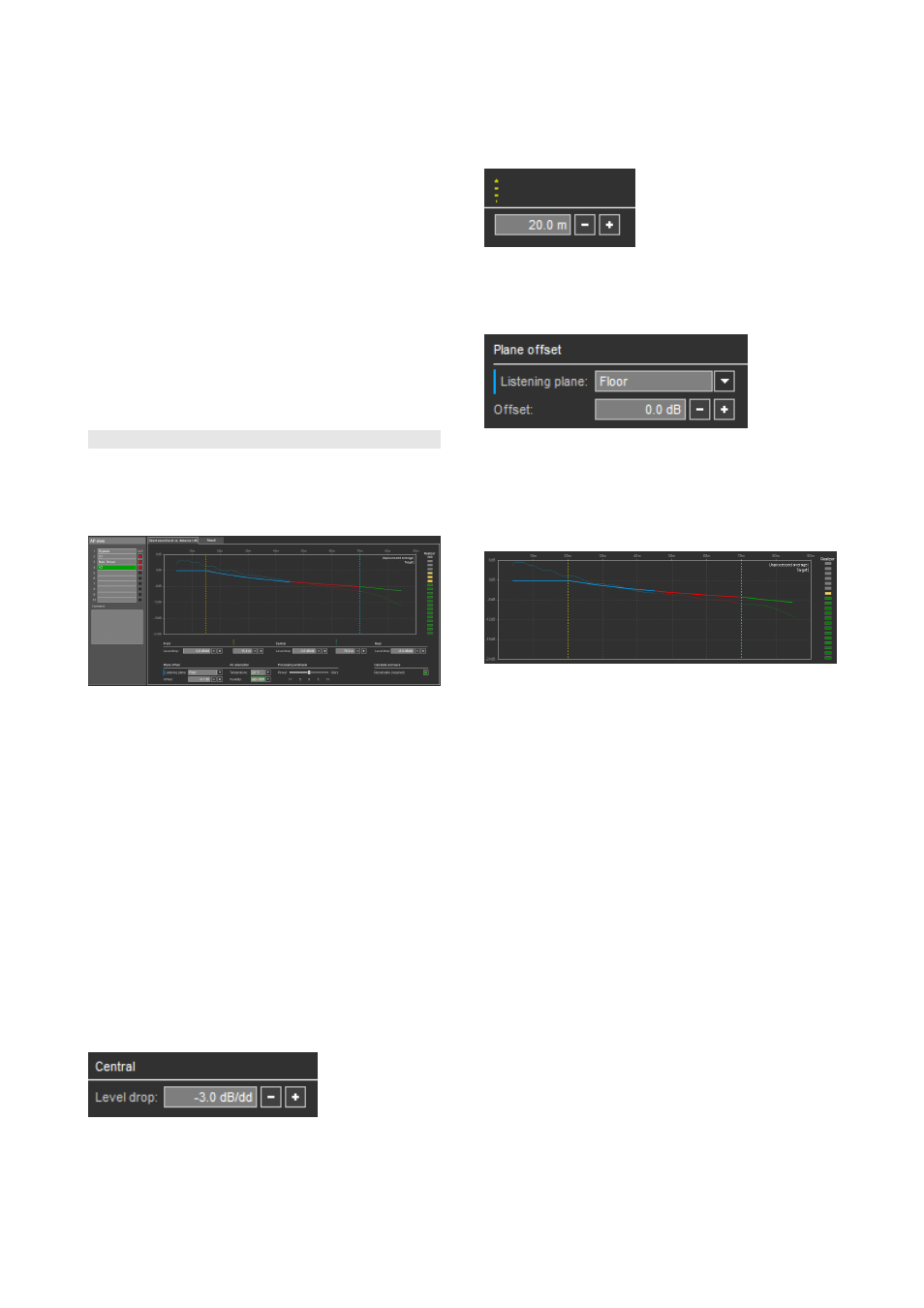
Level drop:
Specifies the desired level drop in dB per doubled distance
for the respective venue area (Front/Central/Rear).
Area borders:
Two distance values setting the borders of the venue areas
(Front/Central/Rear) for which individual level drops can
be defined.
Plane offset:
This parameter allows to define a level offset (positive or
negative) for a specific listening plane.
Direct sound over distance:
The graph shows the current target curve resulting from
these settings as a continuous line. The dotted line displays
the unprocessed level distribution (average level across all
frequency bands).
Realizer:
The Realizer meter indicates the match between target and
unprocessed curve. A good match means the processing
effort is low and the system headroom and coherence will
not be significantly affected by it (green area). A poor
match has the opposite effect and will be indicated by
yellow/orange/red LEDs. Red means the array is not
capable of providing the desired level distribution and the
calculation will be blocked. In this case, either the target
levels or the actual physical array design has to be
changed. Yellow or orange means the system is reaching its
limits and you should not demand too much 'Glory' from it
without sacrificing headroom and coherence.
TI 385 (6.0 EN) d&b Line array design, ArrayCalc V8.x
Page 51 of 54