9 maximum spl and headroom, 10 air absorption, hfc circuit, Maximum spl and headroom – d&b TI 385 d&b Line array design User Manual
Page 27
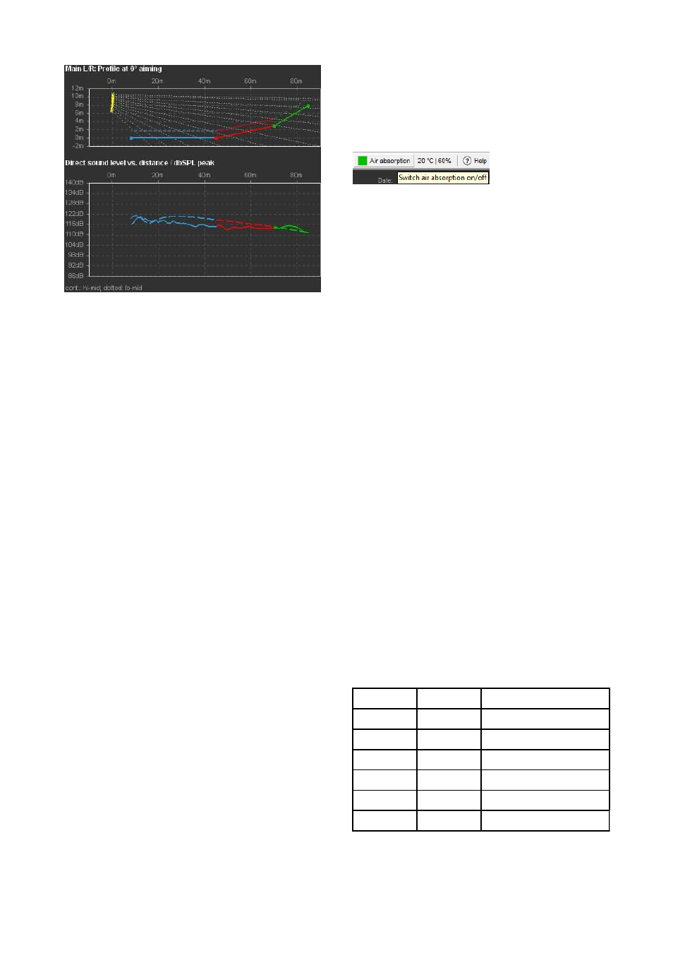
12-deep J8/J12 setup, high directivity
In the second example the system is tuned the opposite way
in order to adapt it to a critical acoustic environment. More
cabinets cover the far field to reduce the drop in level over
distance at high and mid frequencies.
The higher direct sound level at the back of the room will
compensate for the reverberant field and increase the
speech intelligibility.
10.7.9 Maximum SPL and headroom
After the system parameters have been set and the desired
level distribution has been achieved, check the maximum
SPL of the system by increasing the input signal. If any of
the systems reaches its gain reduction level, the respective
GR LED lights up.
If octave frequency bands are selected, the headroom
simulation assumes that band limited pink noise signals of
the selected frequency bands and the given level are
present at each individual amplifier input.
If a broadband signal is selected, the entered level
represents the summed signal level. Therefore the system's
headroom relative to the input signal level is of course
higher when applying individual frequency bands than with
a broadband signal.
To obtain a realistic system headroom estimation with
typical Rock/Pop music program, we recommend that you
use the IEC60268 signal spectrum.
Note: The calculated SPL is an RMS value. In
ArrayCalc versions prior to V7.6.x, this value is a peak
value. To compare the results for sine wave signals, 3dB
have to be added to the RMS value to obtain a peak
value. ArrayCalc constantly monitors the broadband
amplifier headroom and whether the third octave band
level of any cabinet exceeds the maximum possible
level in the respective bands.
10.7.10 Air absorption, HFC circuit
In addition to the overall loss of sound pressure with
increasing distance, a certain amount of the acoustic
energy is absorbed by air. This effect follows a quite
complex function of mainly frequency, humidity and
temperature.
When the Air absorption switch is activated, ArrayCalc
calculates this effect for selectable temperature and
humidity values. The Air absorption switch is located in the
Extras-Options menu and directly accessible from the
toolbar. To define the temperature units, click Extras-
Options and choose between degrees Celsius and
Fahrenheit under Units. The relative humidity can be
specified in 4 steps: "dry-20 %" , "low-40 %", "std-60 %"
and "high-80 %".
Note that in reality there is not much point in specifying
humidity values in more detail based on readings taken at
one position within an audience area. In almost all cases,
this only pretends to be a high accuracy since these
conditions strongly vary with the height above an
audience... and that´s where the sound has to pass
through.
Note: When ArrayProcessing is enabled, the Air
absorption function is permanently active and only the
temperature and humdity settings can be changed.
Compensating for air absorption - HFC function
When air absorption calculation is selected, you can set the
HFC (high frequency compensation) selectors and their
settings will be taken into account in the frequency response
and headroom simulation of the respective cabinets. When
you switch off the air absorption calculation, the settings for
the cabinets will be kept and the HFC drop-down lists will
be disabled. In this case, the HFC settings will not be taken
into account.
That means, by switching the air absorption calculation on
or off, you can verify a useful compensation for the
individual amplifier channels.
The different settings of the HFC correction cover the
following distances according to the individual systems
used:
Series
HFC1
HFC2
J
40 m
80 m
V
30 m
60 m
Y
25 m
50 m
Q
30 m
--
T
25 m
50 m
xA
25 m
50 m
Overview of HFC distance compensation
TI 385 (6.0 EN) d&b Line array design, ArrayCalc V8.x
Page 27 of 54