5 shaping the wavefront using delays – d&b TI 385 d&b Line array design User Manual
Page 34
It is also clearly visible that the behavior is identical in the
direction of the audience area as well as in the direction of
the stage.
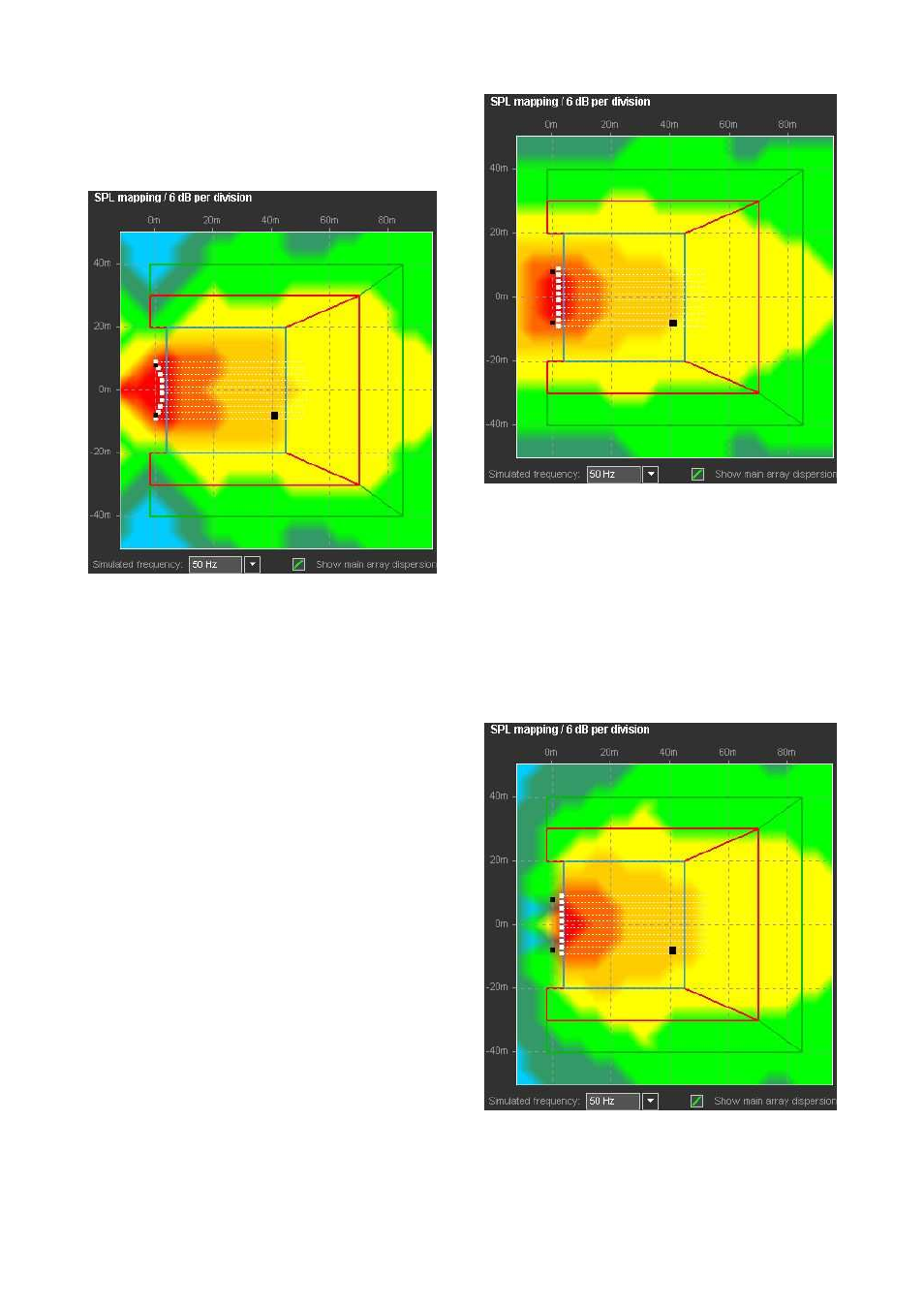
Curving the array physically widens the dispersion, thus
providing a more useful coverage.
50 Hz mapping of a physically curved 10-source SUB array
This arrangement has two significant disadvantages. Firstly,
it occupies positions hardly available for subwoofer
placement in reality; secondly, it creates an energy focus on
the stage center which is very difficult or even impossible to
handle with many open microphones.
10.10.5 Shaping the wavefront using delays
The above examples show that our aim is to achieve the
performance of a curved array towards the audience area,
but without the increased stage levels and with a realistic
space requirement.
Transforming the physical arc into a delay pattern achieves
the desired performance while avoiding the space problem
and reducing the low frequency peak at the center of the
stage by about 6 dB.
50 Hz mapping of 10 delay-arced omnidirectional
subwoofers
Array of directional (cardioid) subwoofers
Distributed SUB arrays with their dispersion designed with a
delayed arc, set up from directional subwoofers (cardioid
or hypercardioid) offer exceptional control possibilities of
the low frequency energy while keeping the on-stage low
frequency level at a minimum. The following plot uses the
identical delay pattern as the one above but the
omnidirectional subwoofers are replaced by cardioid ones.
Note the reduction of the on-stage level of 12 to 18 dB.
50 Hz mapping of 10 cardioid delay-arced subwoofers
Furthermore, directional subwoofers allow to manipulate the
dispersion pattern by rotating the single cabinets about their
vertical axes.
TI 385 (6.0 EN) d&b Line array design, ArrayCalc V8.x
Page 34 of 54