d&b TI 385 d&b Line array design User Manual
Page 18
A superelliptic listening plane starts with a span of
360°and can be moved, rotated and modified to any
possible shape of an ellipse by dragging its start/end
points or by entering data into the input fields in the Venue
editor dialog.
When modifying plane coordinates, the standard shape is
symmetrical around its (front) center point. Only by using
ALT+mouse movement is the symmetry abandoned and
points can be modified individually.
Pressing the ALT key while dragging a plane activates the
Snap to element option. When this option is active, the
corner points of the plane being dragged snap to any other
corner points of the other plane to which it is dragged.
Please note that the height (z) of the snapping corner points
will be adjusted to the height (z) of the corner points of the
plane to which they are snapped.
You can select multiple listening planes and/or obstacles
for editing by pressing the CTRL (Windows) or CMD key
(OS X) while clicking the desired planes and/or obstacles
Alternatively, it is possible to select multiple listening planes
and/or obstacles by dragging a selection rectangle around
them or to select all by pressing CTRL+A (Windows) or
CMD+A (OS X).
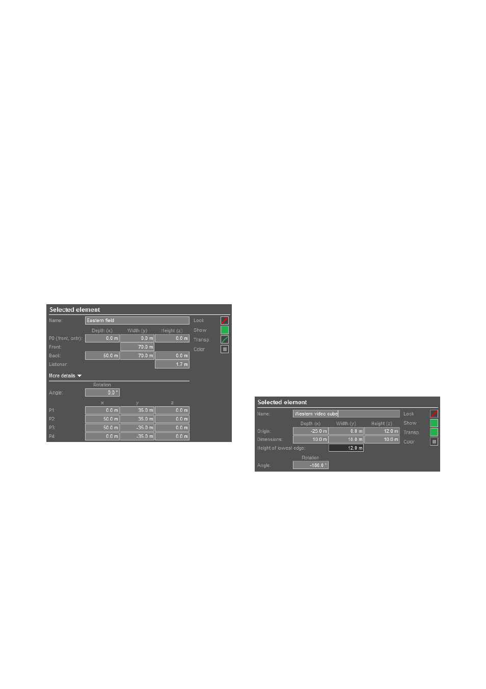
Listening plane properties
A listening plane is selected for viewing and editing its
properties by clicking the plane in one of the diagrams:
Name:
Each plane can be named individually.
Plane coordinates: In the upper section, a simplified plane
definition based on symmetry of the plane itself is possible.
Listener height: Enter the typical height of the listener's ear.
In the More details section below, the three-dimensional
coordinates of each corner point can be accessed
individually. Place the cursor in one of the data input cells
(x,y,z) of a specific point to highlight the respective point in
both the Top view and the Side view diagrams.
Lock: This function protects all dimensional parameters of a
listening plane against editing. Only the name and color of
the listening plane can still be edited when the plane has
been locked.
Show: If a plane is switched off here, its borders are
displayed in dashed lines in the Venue editor. On all other
pages, the plane or its sections are not visible. It is also
excluded from all calculations.
Transparent option:
When a sound from a source hits a plane, it gets absorbed
by the plane. This is indicated by the fact that the main
beams of the relevant cabinets end as soon as they hit the
plane. Listening points on other planes without a direct line
of sight to a source or points which are in the shadow of a
particular plane do not receive any sound from the source.
This feature can be specifically helpful when simulating the
level of under balcony listening positions.
When a plane's Transparent switch is enabled, the plane
will not absorb the sound. In this case, the beams will go
"through" the plane onto any other planes that are located
in its shadow.
When the planes are set to absorbent, the system checks
every single listening point for an acoustic "sightline",
something which requires a considerable amount of
computing time. As a result, to speed up calculation,
listening planes should be switched to Transparent unless
the planes need to be absorbent to check the levels under
balconies, etc. For this reason, in every new plane the
"Transparent" option is enabled as default.
Color: The color of each listening plane with its associated
data such as calculated levels can be defined individually.
Obstacles
A virtually unlimited number of obstacles (screens, displays,
etc.) can be defined. An obstacle is added to the project by
clicking the Obstacle button.
Name: Each obstacle can be named individually
Coordinates: The reference point for all coordinate inputs
is always the geometric center of its base edge (P4-P1; the
one opposite to the grab point). The center of the obstacle's
base edge P4-P1 is defined in the row "Origin". Its
extension in x/y/z is defined in the row "Dimensions"
. An
obstacle can only be symmetrical. x, y and z have to be
positive values, so it always extends upwards from its base
plane.
TI 385 (6.0 EN) d&b Line array design, ArrayCalc V8.x
Page 18 of 54