17 ground stacked setups – d&b TI 385 d&b Line array design User Manual
Page 44
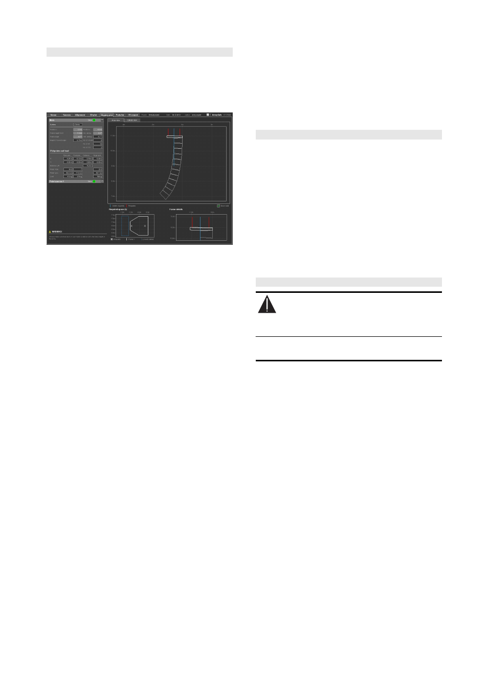
10.15 Rigging plot page
An additional page that displays all mechanical information
such as weights, load conditions, rigging points and
dimensions of line arrays. A rigging plot with this
information for each array in the project should be made
available beforehand for stage and rigging planning.
Rigging plot
For arrays, the Array view shows the overall shape of the
array, its required overall space and frame details.
The Collision view diagram gives an overview of all sources
selected including the overall clearance needed for each
source. A possible collision during setup can be seen here,
as well as the absolute positioning of sources in the room.
The dialog of an array shows the exact x/y coordinates of
the rigging points of each selected array, their relative
distances in x and y directions, the position of possible
single pickpoint support, and the individual pickpoint loads
of each array.
The dialog of a point source group shows the x/y
coordinates of each point source of that particular group.
Print options
You can print out two different views of the rigging plot:
either with detailed data of the selected array or as an
overview plot including all coordinates of the rigging points,
their relative distances and the loads of all arrays in the
project. If the number of arrays/groups of point sources in
the project exceeds 7, the printout extends over more than
one page.
V / Y Flying adapter
A V or Y array with no more than four V-TOP cabinets or six
Y-TOP cabinets allows the optional use of the Z5385 V
Flying adapter / Z5394 Y Flying adapter. If this is possible
for a selected array, the closest pickpoint hole and the
exact (theoretical) distance in cm/in are displayed in the
array data section.
Q Flying adapter
A Q array with no more than three Q-TOP cabinets allows
the optional use of the Z5156 Q Flying adapter. If this is
possible for a selected array, the closest pickpoint hole and
the exact (theoretical) distance in cm/in are displayed in
the array data section.
10.16 Parts list page
ArrayCalc generates a parts list including all cabinets and
rigging components that are required for the specified
single or symmetrical arrays defined in the project. Also
included are the designed SUB array and the cabinets used
for the groups of point sources or columns. The number of
amplifiers is available once you have assigned the cabinets
to the amplifier channels on the Amplifiers page.
Note: Please note that in the Amplifiers section, the
column for each source only indicates the channels used
for that particular source. The 'Total' column indicates
the total number of amplifiers used in the project.
10.17 Ground stacked setups
WARNING!
P
otential risk of personal injury and/or
damage to materials.
Ground stacked arrays must be secured to avoid either
possible movement or tipping over.
When a stacked configuration is selected, the array design
will be reversed. Subwoofers will be placed as lowest
cabinets. A maximum of 8 cabinets can be selected.
As the Flying frame has to be mounted horizontally, the
aiming of the cabinets has to be performed with the help of
splay angles only, starting with the lowest J/V/Q/T cabinet.
There is no Auto splay algorithm available. The height of
the system is defined by the stage height and the number of
subwoofers.
TI 385 (6.0 EN) d&b Line array design, ArrayCalc V8.x
Page 44 of 54