Auxiliary power supply, Communications connection, Connection – CIRCUTOR CDP-0 User Manual
Page 11: Diagrams
CDP
Instruction Manual
11
3.5.- CONNECTION DIAGRAMS
Table 3: Equivalences between the single-phase and three-phase connection.
Equivalence between the single-phase and three-phase connection
Connection Single-phase connection
Three-phase connection
VL1 – IL1
User consumption
Phase 1 consumption
VL2 – IL2
Consumption from the grid
Phase 2 consumption
VL3 – IL3
Power injected by the inverter
Phase 3 consumption
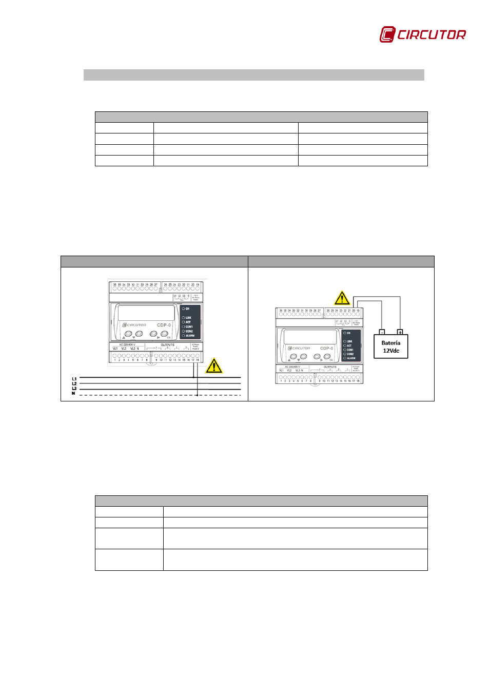
3.5.1. AUXILIARY POWER SUPPLY
The unit has terminals for supplying it either AC voltage (17-18) or DC voltage
(19-20):
AC power supply
DC power supply
Figure 3: AC and DC power supply connection.
3.5.2. COMMUNICATIONS CONNECTION
The CDP has three communications channels referred to as R1, R2 and R3.
Table 4: Description of the communications channels.
Description of the communications channels
Channel
Description of the channel
R1
Ethernet communications channel
R2
Channel for communicating with the inverter:
RS422/RS485/RS232
R3
Channel for communicating with the external measuring parts:
RS485