Verification of external connections, Faulty connection, On 6.5.3 – CIRCUTOR CIRe3 Series User Manual
Page 32
CIR-e
3
Pag 32 of 50
Instructions manual
If the scale or configuration has been changed during a STOP or during a supply lack, when
pressing START, the device will detect the change, will delete the old data file in SD memory
and will generate a new file with the new configuration parameters.
6.5.3 Verification of external connections
In a normal START process using multi-scale E-FLEX clamps, after the user has selected the
clamp scale, the analyzer will start a procedure for testing the goodness of external connections
(check that V and I probes are placed in the right phases). In case of using single-scale clamps,
this checking process starts automatically after pressing the START button. The checking
process is carried out by the unit continuously, regardless of whether it is recording data or not.
The analyzer will indicate faulty connections with the same LED indicators used during for scale
selection, i.e. sc1, sc2 and sc3. During the checking process, if the three LED indicators light
continuously, that means that the connections and sequence are correct. If there are some of
the LED indicators blinking, that denotes that there is some sort of faulty connection or reverse
sequence.
The causes of faulty connections of one or more phases are explained below:
6.5.3.1 Faulty connection
The analyzer can indicate a faulty connection for several reasons. i.e.
-
Voltage sequence error.
-
Current clamp with a wrong connection or reversed sense.
-
The instrument detects a negative power.
-
Power factor (PF) is lower than 0.5 (angle > 60º).
Since a faulty connection can be due to a problem in the connection of the voltage
probes or in current clamps, CIRCUTOR recommends following the procedure
detailed below:
1. Install voltage PROBES and check all connections
2. Install the current clamps and check all connections
Follow this procedure to check whether the flashing of LED indicators is due to an
error in the voltage sequence or to an incorrect connection of the current clamps.
After setting the scale of current clamps and before clamping them on the bus bars or wiring,
we recommend connecting the voltage clamps, to verify their proper connection. After
connecting the voltage clamps, observe the LED indicators L1/sc1, L2/sc2 and L3/sc3, if any
of them are blinking (usually two) this indicates that the cables are placed with wrong phase
sequence. If all the LED indicators lit continuously, it indicates that the connection is correct.
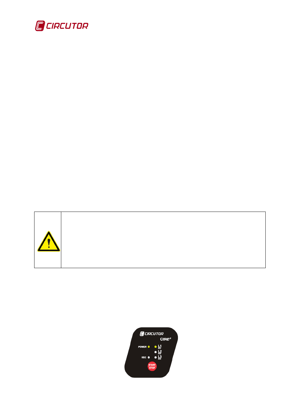
Fig. 6-22 with L2 and L3 blinking, indicates that the connection of voltage clamps in phases
L2 and L3 phases is defective. In this case, we should reverse the connections to L2 and L3.
Fig. 6-22.- Wrong connection indication (L2 and L3 blinking)