CIRCUTOR CIRe3 Series User Manual
Page 28
CIR-e
3
Pag 28 of 50
Instructions manual
the desired current range. Do it by pressing the button START/STOP to select sc1, sc2 or sc3
(see paragraph 6.5.2 I case of clamps E-FLEX 54 cm). After scale selection, the device will start
the boot sequence recognized by the sequential ignition of LEDs L1, L2, L3 and then the
POWER LED. After the boot process, the instrument starts a connection error verification
process of the voltage probes, as explained in section 6.5.3 of this manual.
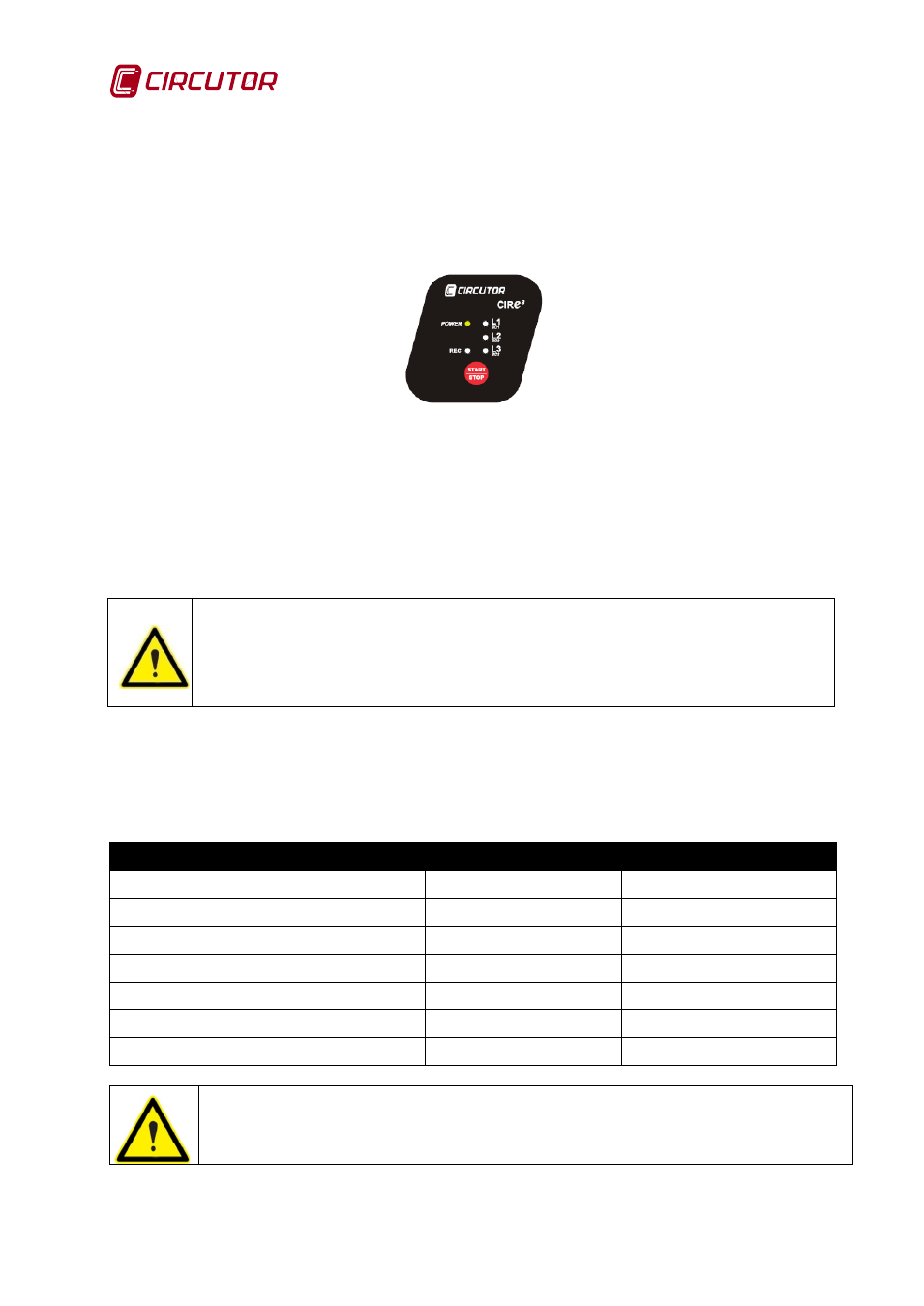
Once the boot sequence is finished, the device indicates that is powered by lighting POWER
LED
Fig. 6-18.- LED indicators showing the status of CIR-e
3
After the POWER LED lights, connect the phase voltage probes L1, L2, L3. If the analyzer must
be powered from the voltage probes, this is possible by connecting the supply cables to the
voltage probes.
Before powering the unit, it is important to connect the current clamps (even if the current scale
is not configured), since the analyzer will identify the current sensors immediately after it is
powered.
If the unit is connected to the supply and the current clamps in connector “A” are
not plugged in, the analyzer will be configured assuming that the current clamps
have a nominal primary current of 5 A. To configure a different scale, unplug the
analyzer, so that it can reset the scale selection process, plug the desired current
clamps and connect the analyzer again to supply.
The procedure to select the current scale when using multi-scale current sensors is explained in
detail in section 6.5.2, of this manual.
To supply and connect the analyzer probes correctly, respect the phase sequence, as shown on
Table 6-1
Table 6-1.- Color code of voltage cables
PHASE
EUROPEAN
RYBLB
Phase reference
Wire colour
Wire colour
(L 1) PHASE 1
BLACK
RED
(L 2) PHASE 2
RED
YELLOW
(L 3) PHASE 3
YELLOW
BLUE
(N) NEUTRAL
BLUE
BLACK
Auxiliary supply
BROWN
BROWN
Auxiliary supply
GREEN
GREEN
The colours of voltage phases can change according to the colour scheme selected
in the device code. The following table lists the references for each phase of the
different colours.
The analyzer's connection diagrams show the final voltage and current sensor connections. Do