Setup elements, Fpp configuration/max ii bypass dip switch, Setup elements –19 – Altera Transceiver Signal Integrity Development Kit, Stratix V GT Edition User Manual
Page 27: Fpp configuration/max ii bypass dip switch –19
Chapter 2: Board Components
2–19
Configuration, Status, and Setup Elements
May 2014
Altera Corporation
Transceiver Signal Integrity Development Kit
Stratix V GT Edition Reference Manual
lists the board-specific LEDs component references and manufacturing
information.
Setup Elements
The development board includes several different kinds of setup elements. This
section describes the following setup elements:
■
FPP configuration or MAX II bypass DIP switch
■
Program select jumper
■
MAX II reset push button
■
CPU reset push button
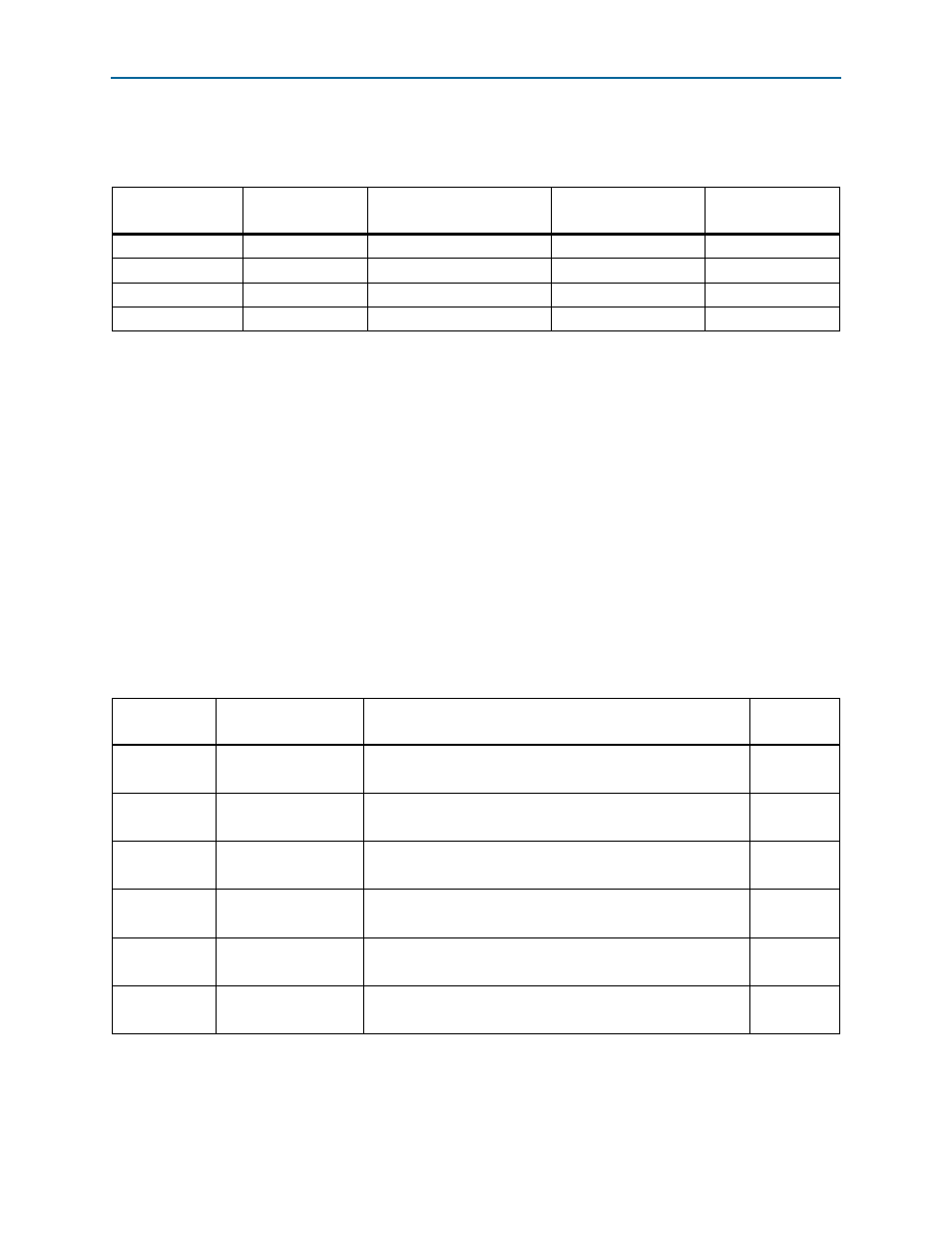
FPP Configuration/MAX II Bypass DIP Switch
The FPP configuration or MAX II bypass DIP switch (S7) controls the FPP
configuration mode and also selects the MAX II CPLD to be in the JTAG chain.
lists the switch settings and descriptions.
Table 2–9. Board-Specific LEDs Component References and Manufacturing Information
Board Reference
Description
Manufacturer
Manufacturer
Part Number
Manufacturer
Website
D8, D10-D17
Green LEDs
Lumex Inc.
SML-LX1206GC-TR
D9
Red LED
Lumex Inc.
SML-LX1206IC-TR
D3
Blue LED
Lumex Inc.
SML-LX1206USBC-TR
D7
Amber LED
Lite-On
LTST-C150KYKT
Table 2–10. FPP Configuration/MAX II Bypass DIP Switch Settings
Board
Reference (S7)
Schematic Signal
Name
Description
Default
1–12
MSEL0
ON : Logic 0 is selected for MSEL0
OFF : Logic 1 is selected for MSEL0
ON
2–11
MSEL1
ON : Logic 0 is selected for MSEL1
OFF : Logic 1 is selected for MSEL1
ON
3–10
MSEL2
ON : Logic 0 is selected for MSEL2
OFF : Logic 1 is selected for MSEL2
OFF
4–9
MSEL3
ON : Logic 0 is selected for MSEL3
OFF : Logic 1 is selected for MSEL3
ON
5–8
MSEL4
ON : Logic 0 is selected for MSEL4
OFF : Logic 1 is selected for MSEL4
ON
6–7
MAX_BYPASS
ON : MAX II CPLD EPM2210 System Controller in-chain
OFF : Bypass MAX II CPLD EPM2210 System Controller
ON