Push button switches – Altera Transceiver SI User Manual
Page 33
Altera Corporation
Getting Started User Guide
A–5
June 2006
Transceiver Signal Integrity Development Kit, Stratix II GX Edition
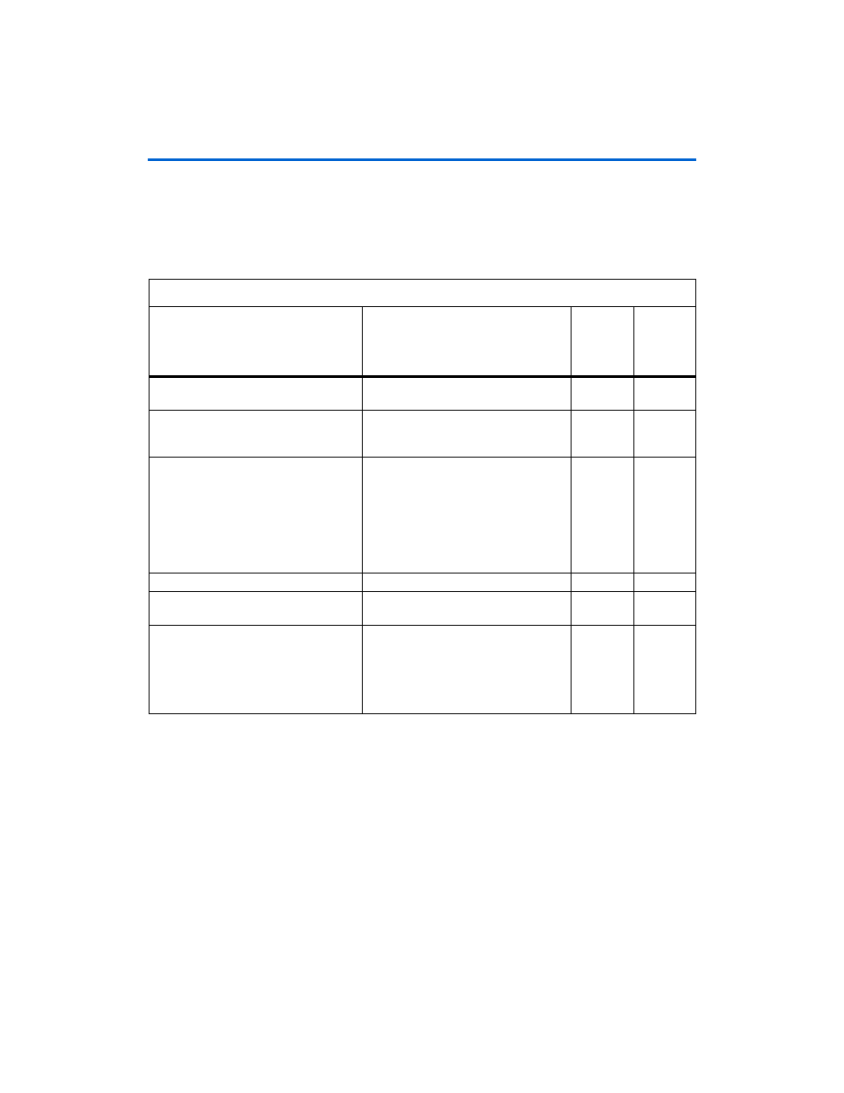
Push Button Switches
Table A–3
lists the push button switch signal names, describes the
functionality, lists the board reference numbers, and FPGA pin
connection.
Table A–3. Push Button Switches
Push Button Switch Name
Description
Board
Reference
Number
Connected
to FPGA
Pin
Number
resetn
(system reset)
Performs a reset on the transceiver and
also the entire design.
S1
AD28
generator_checker_reset_switch
Performs a reset on the data generators
and error checkers. The push button will
also reset the error counters.
S2
AF34
change_PMA_switch
Based on the selection of the PMA
Controls DIP switch, the push button sets
the value for either VOD, preemphasis,
DC gain or equalization.
Every time the push button is pressed, the
value is incremented.
W
hen the
maximum value is reached, the value
starts from zero.
S3
AF33
insert_error_switch
Inserts one bit error in the transmit data.
S4
AE30
clear_error_counter_switch
The push button resets the error
counters.
S5
AE29
show error count
Displays the most significant byte of the
error. For example if the error count is
02FF
, when the push button is asserted
02
is displayed until the button is
de-asserted. Refer to
Table A–1 on
page A–2
for additional information.
S6
AH20