Thermal analysis, Thermal analysis -9 – Altera PowerPlay Early Power Estimator User Manual
Page 19
•
on page 3-40
Thermal Analysis
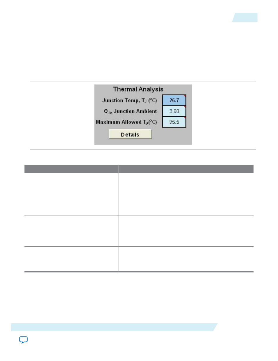
The following figure shows the Thermal Analysis section in the Main worksheet, including the junction
temperature (T
J
), total junction-to-ambient thermal resistance (θ
JA
), and the maximum allowed ambient
temperature (T
A
) values. For details about the values of the thermal parameters not listed in this user
guide, click the Details button.
Figure 3-5: Thermal Analysis Section of the PowerPlay EPE Spreadsheet
Table 3-3: Thermal Analysis Section Information
Column Heading
Description
Junction Temp, T
J
(°C)
The device junction temperature estimation based on
supplied thermal parameters.
The junction temperature is determined by dissipating the
total thermal power through the top of the chip and through
the board (if selected). For detailed calculations, click the
Details button.
θ
JA
Junction-Ambient
The junction-to-ambient thermal resistance between the
device and ambient air (in °C/W).
Represents the increase in temperature between ambient and
junction for every W of additional power dissipation.
Maximum Allowed T
A
(°C)
A guideline for the maximum ambient temperature (in °C)
that you can subject the device to without violating the
maximum junction temperature, based on the supplied
cooling solution and device temperature grade.
You can directly enter or automatically compute the junction temperature based on the information
provided. To enter the junction temperature, select User Entered T
J
in the Input Parameters section. To
automatically compute the junction temperature, select Auto Computed T
J
in the Input Parameters
section.
When automatically computing the junction temperature, the ambient temperature, airflow, heat sink
solution, and board thermal model of the device determine the junction temperature in °C. Junction
UG-01070
2015.01.20
Thermal Analysis
3-9
PowerPlay Early Power Estimator Worksheets
Altera Corporation