Figure 3–25 – Altera PowerPlay Early Power Estimator User Manual
Page 49
Altera Corporation
3–35
May 2008
PowerPlay Early Power Estimator For Arria GX FPGAs
Using the PowerPlay Early Power Estimator
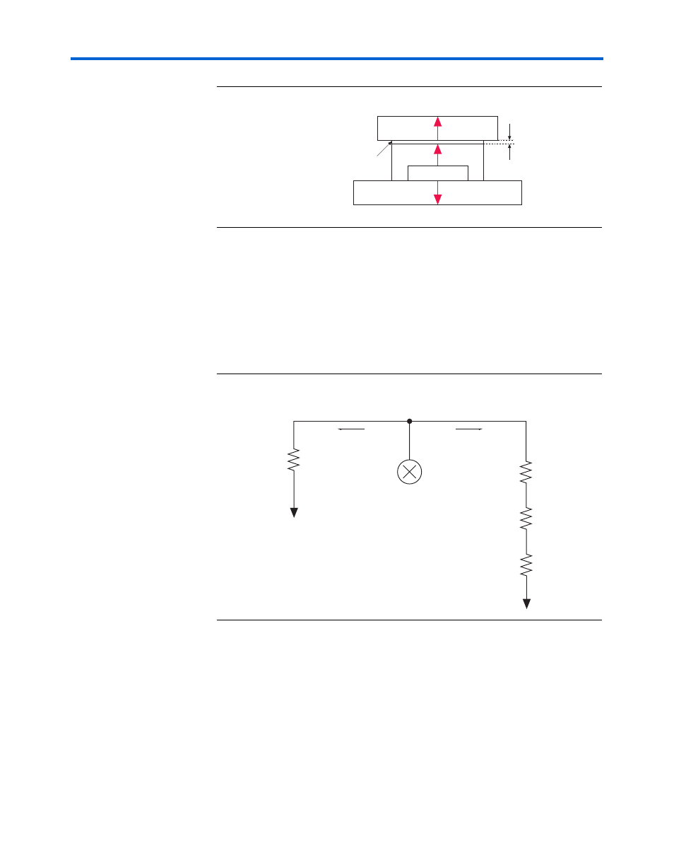
Figure 3–25. Thermal Representation with Heat Sink
In the model used in the PowerPlay Early Power Estimator, power can be
dissipated through the board or through the case and heat sink. The
thermal resistance of the path through the board is referred to as the
junction-to-board thermal resistance (
θ
JA
). The thermal resistance of the
path through the case, thermal interface material and heat sink is referred
to as the junction-to-ambient thermal resistance (
θ
JA
).
Figure 3–26
shows
the thermal model for the PowerPlay Early Power Estimator.
Figure 3–26. Thermal Model for the PowerPlay Early Power Estimator with a
Heat Sink
If you want the PowerPlay Early Power Estimator spreadsheet thermal
model to take the junction-to-board thermal resistance (
θ
JB
) into
consideration, set the Board Thermal Model to either “Typical” or
“Custom.” A Typical board thermal model sets
θ
JB
to a value based on the
package and device selected. If you choose a Custom board thermal
model, you must specify a value for
θ
JB
. If you do not want the PowerPlay
Early Power Estimator spreadsheet thermal model to take the
θ
JB
resistance into consideration, set the Board Thermal Model to “None
Heat Sink
Case
Device
Board
Thermal Interface Material
θ
JB
θ
JC
θ
SA
Thermal Representation with Heat Sink
θ
CS
θ
JC
θ
CS
θ
SA
θ
JB
T
J
T
B
T
J
T
C
T
S
T
A
Power (P)
Power (P)
Heat Source