Digital signal processing (dsp) – Altera PowerPlay Early Power Estimator User Manual
Page 27
Altera Corporation
3–13
May 2008
PowerPlay Early Power Estimator For Arria GX FPGAs
Using the PowerPlay Early Power Estimator
Digital Signal Processing (DSP)
Arria GX devices have dedicated DSP blocks that can implement
high-speed parallel processing optimized for DSP applications.
High-speed DSP blocks provide dedicated implementation of
multipliers,
multiply_accumulate functions, and finite impulse
response (FIR) filters. DSP blocks are ideal for implementing DSP
applications that need high data throughput. The Digital Signal
Processing (DSP)
section in the PowerPlay Early Power Estimator
spreadsheet provides power information for Arria GX DSP blocks.
Each row in the DSP section represents a DSP design module where all
instances of the module have the same configuration, clock frequency,
toggle percentage and register usage. If some (or all) DSP or multiplier
instances have different configurations, you need to enter the information
in different rows. You must enter the following information for each DSP
or multiplier module:
■
Configuration
■
Clock frequency (f
MAX
) in MHz
■
Number of instances
■
Toggle percentage of the data outputs
■
Whether or not the inputs and outputs are registered
■
Whether or not the module is pipelined
f
For more information on Arria GX DSP block configurations, refer to the
DSP Blocks in Arria GX Devices chapter in volume 2 of the Arria GX Device
Handbook.
Table 3–4
describes the values that need to be entered in the DSP section
of the PowerPlay Early Power Estimator.
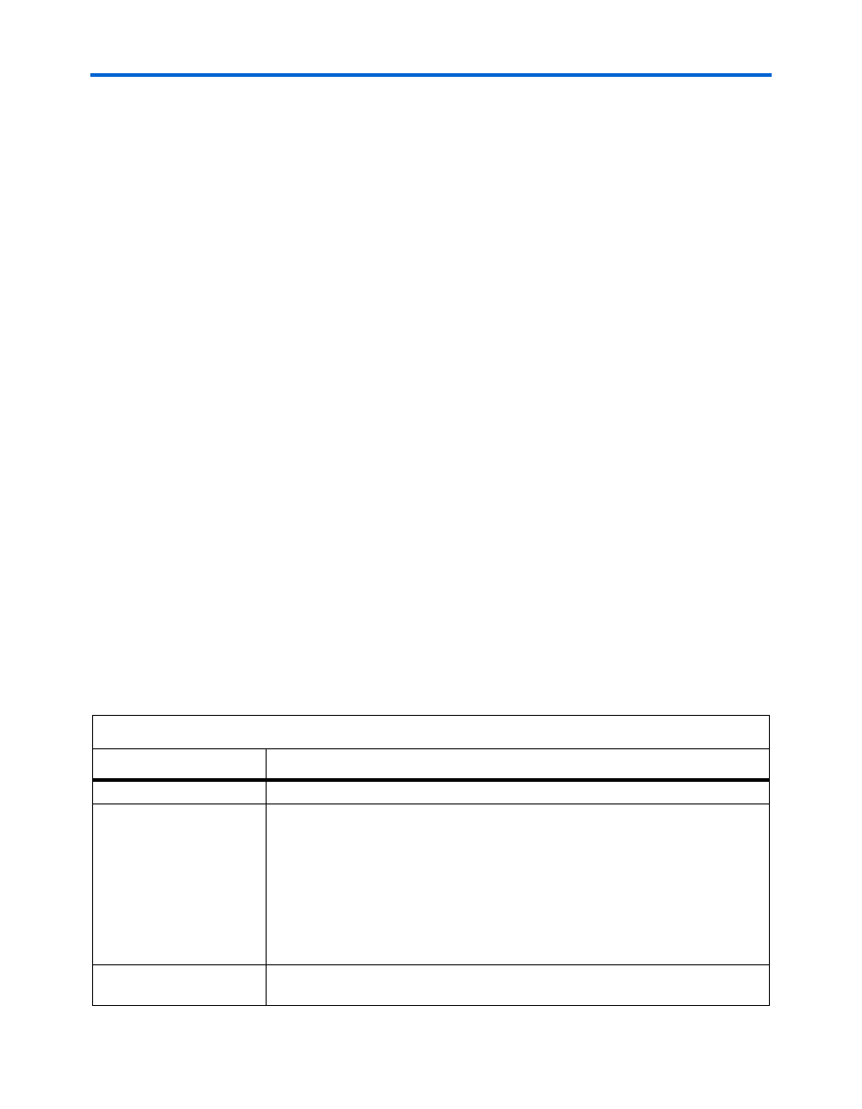
Table 3–4. DSP & Multiplier Section Information (Part 1 of 2)
Column Heading
Description
Module
Enter a name for the DSP module in this column. This is an optional value.
Configuration
Select the DSP block configuration. The following configurations are offered:
●
9 × 9 simple multiplier
●
18 × 18 simple multiplier
●
36 × 36 simple multiplier
●
18 × 18 multiplier-accumulator
●
9 × 9 two-multiplier-adder
●
18 × 18 two-multiplier-adder
●
9 × 9 four-multiplier-adder
●
18 × 18 four-multiplier-adder
Clock Frequency (MHz)
Enter the clock frequency for the module in MHz. This value is limited by the
maximum frequency specification for the device family.