Ethernetblaster ii ethernet jack connection, Ethernetblaster plug connection – Altera EthernetBlaster II User Manual
Page 26
3–2
Chapter 3: EthernetBlaster II Communications Cable Specifications
EthernetBlaster II Hardware Connections
EthernetBlaster II Communications Cable User Guide
January 2014
Altera Corporation
EthernetBlaster II Ethernet Jack Connection
The Ethernet cable Ethernet jack connects to the EthernetBlaster II communications
cable Ethernet port.
shows the Ethernet jack pin number designations.
EthernetBlaster Plug Connection
The 10-pin female plug connects to a 10-pin male header on the circuit board
containing the target device (
Table 3–2
lists the 10-pin female plug pin names and the corresponding programming
mode.
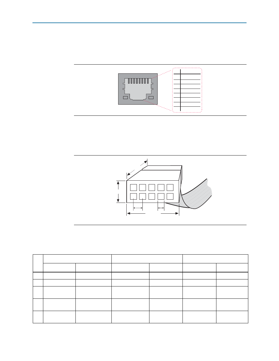
Figure 3–1. Ethernet Jack Pin Number Designations
Pin
Signal
1
2
3
4
5
6
7
8
TxData +
TxData -
RecvData +
-
-
RecvData -
-
-
8
1
Figure 3–2. EthernetBlaster 10-Pin Female Target-Side Plug Dimensions
0.250 Typ.
0.700 Typ.
0.425 Typ.
0.100 Sq.
10
9
8
7
6
5
4
3
2
1
0.025 Sq.
Dimensions are shown in inches. Spacing between pin centers is 0.1 inches.
Table 3–2. EthernetBlaster Female Plug Signal Names and Programming Modes (Part 1 of 2)
Pin
AS Mode
PS Mode
JTAG Mode
Signal Name
Description
Signal Name
Description
Signal Name
Description
1
DCLK
Clock signal
DCLK
Clock signal
TCK
Clock signal
2
GND
Signal ground
GND
Signal ground
GND
Signal ground
3
CONF_DONE
Configuration
done
CONF_DONE
Configuration
done
TDO
Data from
device
4
VCC(TARGET)
Target power
supply
VCC(TARGET)
Target power
supply
VCC(TARGET)
Target power
supply
5
nCONFIG
Configuration
control
nCONFIG
Configuration
control
TMS
JTAG state
machine control