Ethernetblaster ii hardware connections, Voltage requirements, Ethernetblaster ii hardware connections –1 – Altera EthernetBlaster II User Manual
Page 25: Voltage requirements –1
January 2014
Altera Corporation
EthernetBlaster II Communications Cable User Guide
3. EthernetBlaster II Communications
Cable Specifications
This chapter provides comprehensive information about the EthernetBlaster II
communications cable, including the following:
■
“EthernetBlaster II Hardware Connections”
■
“Operating Conditions” on page 3–4
EthernetBlaster II Hardware Connections
The EthernetBlaster II cable connects to an Ethernet cable with an RJ45 jack to a
10/100/1000Base-T Ethernet hub/switch (using a straight 8-wire data cable) or a
10/100/1000Base-T Ethernet port of a PC (using a straight 8-wire or a crossover data
cable). Depending on your connection (remote or direct), data is downloaded through
the EthernetBlaster II communications cable to the circuit board using the connections
described in this section.
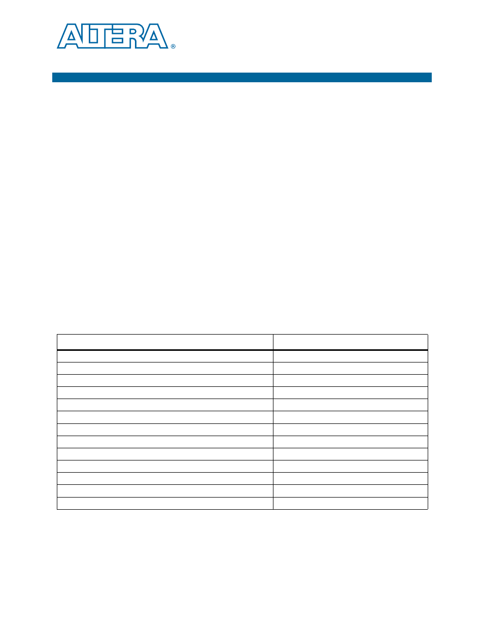
Voltage Requirements
You must connect the EthernetBlaster II
V
CC(TARGET)
pin to a specific voltage for the
device being programmed. Connect pull-up resistors to the same power supply as the
EthernetBlaster II V
CC(TARGET).
Table 3–1
lists the EthernetBlaster II V
CC
voltage
requirements.
Table 3–1. EthernetBlaster II V
CC(TRGT)
Pin Voltage Requirements
Device Family
EthernetBlaster II V
CC
Voltage Required
MAX
®
II devices
As specified by V
CCIO
of Bank 1
MAX 7000AE and MAX 3000A devices
3.3 V
MAX 7000B device
2.5 V
Cyclone
®
V devices
V
CCPD
Cyclone IV devices
V
CCA
Cyclone III devices
As specified by V
CCA
or V
CCIO
Stratix
®
V, Stratix IV, Stratix III, Stratix II devices
V
CCPD
Arria
®
V, Arria II GX, and Arria GX devices
V
CCPD
Cyclone II, Cyclone devices
As specified by V
CCIO
EPC2 devices
3.3 V
EPC4, EPC8, and EPC16 devices
3.3 V
EPCS1, EPCS4, EPCS16, EPCS64, and EPCS128 devices
3.3 V
Stratix devices
As specified by V
CCSEL