Measuring power, Measuring power –2 – Altera Cyclone III FPGA Starter Kit User Manual
Page 24
4–2
Altera Corporation
Cyclone III FPGA Starter Kit User Guide
July 2010
Measuring Power
The design used for power measurement is a replicated set of randomly
filled ROMs that feed a multiplier block and a shift register that is fed by
a signal that changes every clock cycle.
Tables 4–2
and
show the
power state which represent the percent of the full design used. As
compiled, this full design uses:
■
Logic elements: 22,493/24,624 (91%)
■
Combinational functions: 1,961/24,624 (8%)
■
Dedicated logic registers: 21,133/24,624 (86%)
■
Total registers: 21,133
■
Total pins: 73/216 (34%)
■
Total memory bits: 524,288/608,256 (86%)
■
Embedded Multiplier 9-bit elements: 128/132 (97 %)
■
Total PLLs: 1/4 (25%)
Measuring
Power
The example design is located in
<kit install>\examples\cycloneIII_3c25_start_power_demo. Configure
the FPGA with the .sof found in the directory.
1
The input clock (i_clk PIN_B9) is the 50-MHz oscillator on the
board, which generates the input clock for the reference design
through a PLL
f
For more information on configuring the FPGA, refer to
the FPGA Using the Quartus II Programmer” on page 2–3
Current sense resistors (0.010 ± 1%) are installed at locations JP6 (FPGA
core power) and JP3 (FPGA I/O power + other device I/O power). With
a digital multimeter set to mV measurement range, the resistor at location
JP6 measures the core power. The resistor at location JP3 measures the
I/O power. To measure the current being used in various configurations,
use the following steps:
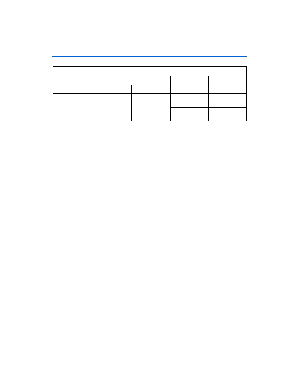
Table 4–3. LEDs Power State (Resources)
Displays
LEDs
State
% of Design Used
MSB
LSB
Resources
LED4
LED3
00
25%
01
50%
10
75%
11
100%