Commissioning, Wiring, General wiring guidelines – Pilz PNOZ mc3p Profibus 2 User Manual
Page 19: Connecting the supply voltage, Profibus dp interface, 6commissioning, 1 wiring, 1 general wiring guidelines, 2 connecting the supply voltage, 3 profibus dp interface
Pilz GmbH & Co. KG, Felix-Wankel-Straße 2, 73760 Ostfildern, Germany
Telephone: +49 711 3409-0, Telefax: +49 711 3409-133, E-Mail: [email protected]
6-1
6.1
Wiring
6
Commissioning
6
6000
Commissioning
Commissioning
6-
6.1
Wiring
6100
Wiring
6-
6.1.1
General wiring guidelines
General wiring guidelines
6-
Verdrahtung_multi_Modul
The wiring is defined in the circuit diagram of the PNOZmulti Configura-
tor.
Note:
Information given in the "Technical details" must be followed.
Verdrahtung_Montageschiene mit Schutzerde verbinden
Always connect the mounting rail to the protective earth via an earth-
ing terminal. This will be used to dissipate hazardous voltages in the
case of a fault.
Verdrahtung_Netzteil_sichere_Trennung
The power supply must meet the regulations for extra low voltages
with safe separation.
6.1.2
Connecting the supply voltage
Connecting the supply voltage
6-
Verdrahtung_multi_Feldbus_Versorgungsspannung
Connect the supply voltage to the base unit:
Terminal 24 V and A1 (+): + 24 VDC
Terminal 0 V and A2 (-): 0 V
6.1.3
PROFIBUS DP interface
PROFIBUS DP interface
6-
Verdrahtung
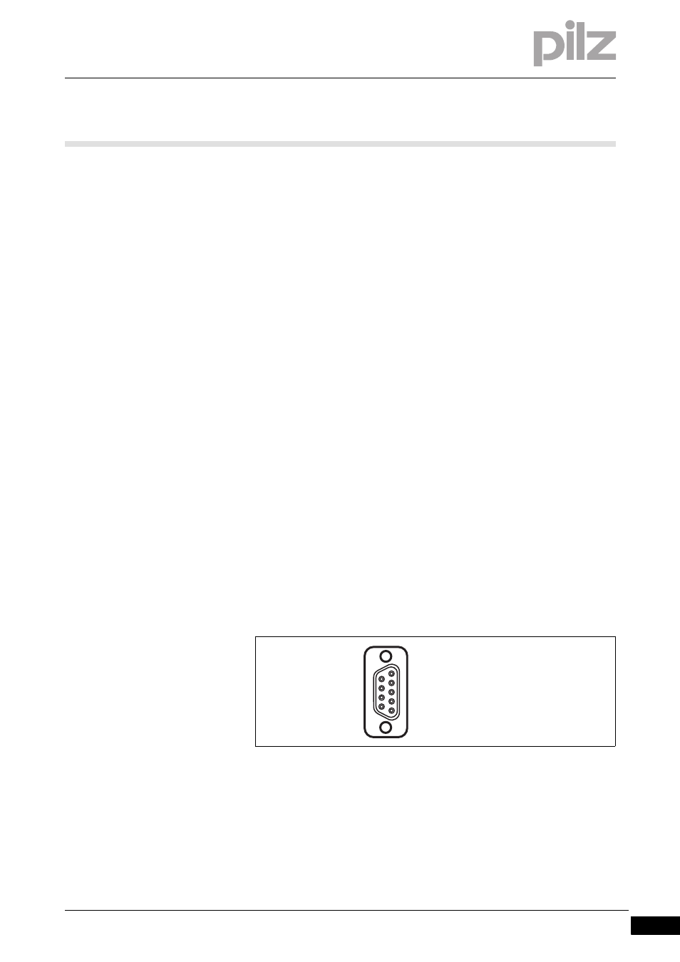
It is possible to define which outputs on the control system will commu-
nicate with PROFIBUS-DP. The connection to PROFIBUS-DP is made
via a female 9-pin D-Sub connector in accordance with the guidelines of
the PROFIBUS User Group (PNO).
n.c. = not connected
Please note the following when connecting to PROFIBUS-DP:
Only use metal plugs or metallised plastic plugs
Twisted pair, screened cable must be used to connect the interfaces
1
5
9
6
1: n.c.
2: n.c.
3: B (RxD/TxD-P)
4: CNTR-P
5: DGND
6: VP
7: n.c.
8: A (RxD/TxD-N)
9: n.c.