Pilz PNOZ e1p 24VDC 2so User Manual
Pnozelog, Fault diagnostics
PNOZelog
1001137-EN-01-2008-03
Fault diagnostics
Pilz GmbH & Co. KG, Sichere Automation, Felix-Wankel-Straße 2, 73760 Ostfildern, Germany, Telephone: +49 711 3409-0, Telefax: +49 711 3409-133, E-Mail: [email protected]
During operation, 3 LEDs indicate the units’
operating status and the fault conditions.
The unit is ready for operation when:
● The “POWER” LED lights up
and
● The LEDs “CH.1” and “CH.2” are both lit
(high signal at the safety outputs)
or
● The LEDs “CH.1” and “CH.2” are both
out (low signal at the safety outputs).
LED CH.1 is assigned to safety output 14,
LED CH.2 to safety output 24.
INFORMATION
Supply interruptions lasting longer
than 20 ms are detected as an error.
The LEDs indicate an error and the
safety outputs carry a low signal. The
plant or machinery driven via the
safety outputs will be shut down. The
unit can only be restarted by
switching the supply voltage off and
then on again.
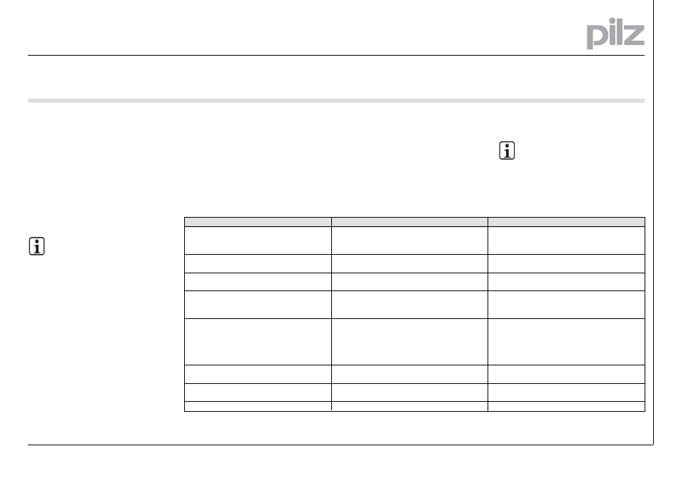
LED
LEDs unlit
POWER flashing
PNOZ e1p: CH.1 and Ch.2 periodically flash at
the same time
All units except
except
except
except
except PNOZ e6.1p, PNOZ e6vp: CH.1
and CH.2 flash alternately
PNOZ e6.1p, PNOZ e6vp: CH.1 and CH.2 flash
alternately
PNOZ e2.1p, PNOZ e2.2p: CH.1 or
or
or
or
or CH.2 flashes
briefly (50 ms on, 250 ms off)
PNOZ e2.1p, PNOZ e2.2p: CH.1 and
and
and
and
and CH.2
flash briefly (50 ms on, 250 ms off)
CH.1 or CH.2 flash a code
Error
Supply voltage is missing, too low, wrongly
connected
Unknown operating mode, initialisation phase, start
not executed
Error in the wiring of input circuit S11, S12, S21,
S22
1.) Feedback loop open on start-up
2.) Only one channel of the input circuit is open or
is partially operated
1.) Feedback loop open on start-up
2.) Only one channel of the input circuit is open or
is partially operated
3.) External feedback loop closed on start-up, but
internal feedback loop faulty
Simultaneity conditions not met
A pushbutton is defective or there is a wiring error
Error coding, see Table 3
Remedy
Apply supply voltage: A1 - +24 VDC and
A2 - 0 VDC
Permitted voltage range: 19.2 ... 30 VDC
Depending on operating mode: Press reset button
or perform start-up test
Rectify wiring error, restart unit
1.) Close feedback loop, open input circuit, start
unit again
2.) Open both input circuit channels
1.) Close feedback loop, open input circuit, start
unit again
2.) Open both input circuit channels
3.) No remedy available to user - send unit to Pilz
Release the two-hand button and press it again.
Change pushbutton or rectify wiring error
See Table 3
Table 1: Display of fault conditions
Errors
Fault conditions are indicated by flashing
the LEDs. Some errors are displayed
through periodic flashing (see Table 1); with
other errors it is possible to establish an
error code through the number of flashes
(Table 2).
These errors are always indicated by three
short flashes at LED CH.1 or CH.2. After a
longer pause, the LED will then flash at one
second intervals. The number of LED
flashes corresponds to a digit in the error
code. The error code can consist of up to 4
digits. The digits are separated by a longer
period without flashing. The entire sequence
is constantly repeated.
The error code can also be read into a PLC
via the diagnostic output. In this case the
error code will appear as a hexadecimal
sequence. The process of reading and
transferring data to a PLC is described in
the PLC Drivers manual.
INFORMATION
Leading zeros are not transmitted.
Error code 0: 16 flashes
- PNOZ e1vp 10/24VDC 1so 1so t PNOZ e1vp 300/24VDC 1so 1so t PNOZ e1.1p 24VDC 2so PNOZ e3vp 10/24VDC 1so 1so t PNOZ e3vp 300/24VDC 1so 1so t PNOZ e3.1p 24VDC 2so PNOZ e5.11p 24VDC 2so PNOZ e5.13p 24VDC 2so PNOZ e6.1p 24VDC 4n/o 2so PNOZ e6vp 24VDC 4n/o 1so 1so t PNOZ e1p C 24VDC 2so PNOZ e1vp C 10/24VDC 1so 1so t PNOZ e1vp C 300/24VDC 1so 1so t PNOZ e1.1p C 24VDC 2so PNOZ e3vp C 10/24VDC 1so 1so t PNOZ e3vp C 300/24VDC 1so 1so t PNOZ e3.1p C 24VDC 2so PNOZ e5.11p C 24VDC 2so PNOZ e5.13p C 24VDC 2so PNOZ e6.1p C 24VDC 4n/o 2so PNOZ e6vp C 24VDC 4n/o 1so 1so t PNOZ e2.2p 24VDC 2so PNOZ e2.1p 24VDC 2so PNOZ e2.2p C 24VDC 2so PNOZ e2.1p C 24VDC 2so PNOZ e4.1p 24VDC 2so PNOZ e4vp 10/24VDC 1so 1so t PNOZ e4.1p C 24VDC 2so PNOZ e4vp C 10/24VDC 1so 1so t