System verification tests, Preliminary setup, Testing the generator – Dukane ULTRASONIC GENERATOR/POWER SUPPLY LS 403-574-01 User Manual
Page 63: De f, Hg a, Step 5. mode key tests a. set mode key, Will be yellow. b. press the test, Will be green. d. press the test key, Figure 7 - 1 rear panel ac breaker/switch, Figure 7 - 2 front panel power test
Page 57
Section 7 – System Operational Testing
Dukane Manual Part No. 403-574-01
System Verification Tests
Preliminary Setup
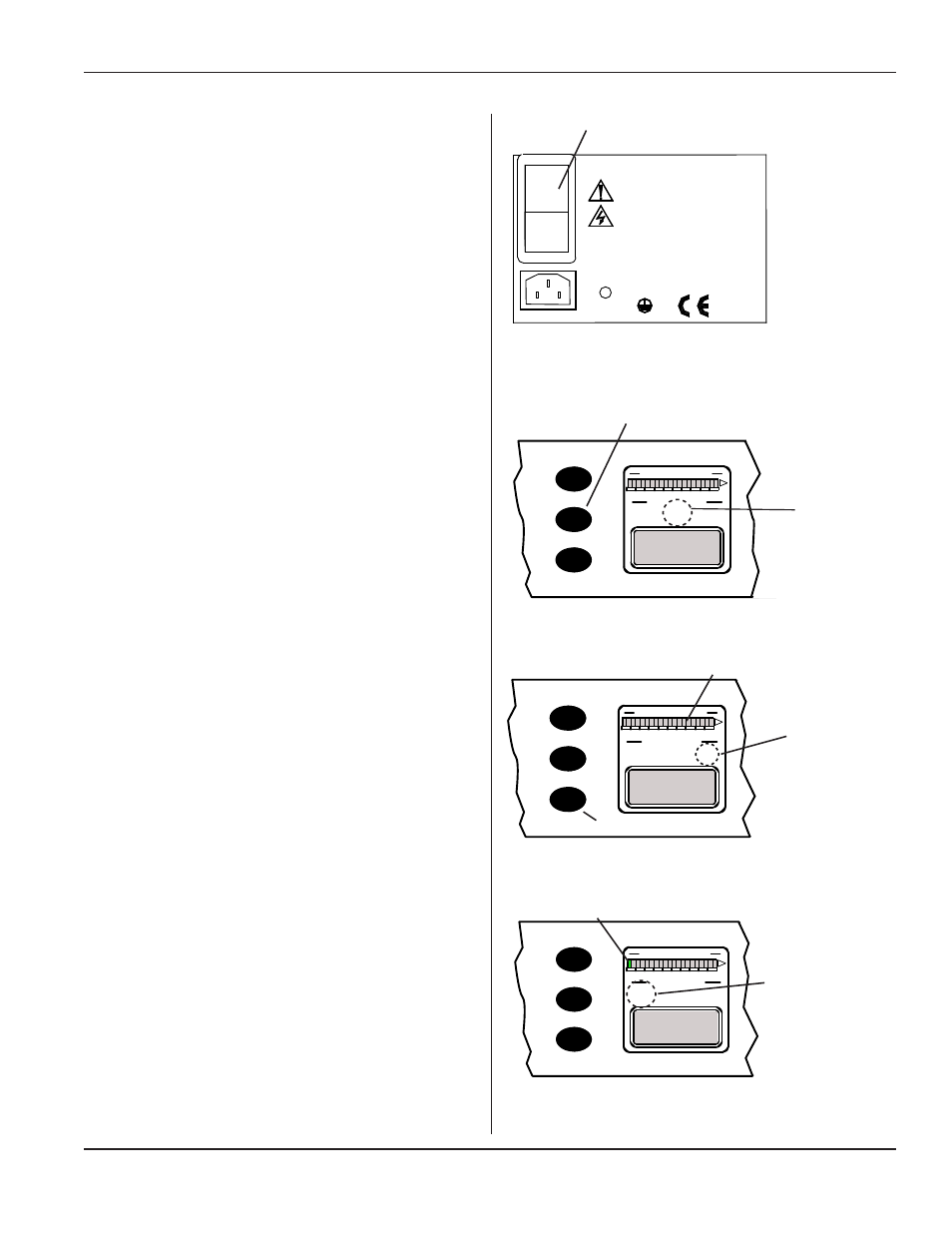
Step 1. Plug in the AC line cord to the correct AC
power outlet. See Table 11 -II for the model
power requirements.
Step 2. Attach a compatible ultrasonic probe to the
ultrasound output connector - J1.
Step 3. Activate the AC Breaker/Switch
A
to the ON
position.
Testing the Generator
(Complete steps 1-3 above, and then continue with
steps 4, 5, and 6 below.)
Step 4. The POWER TEST indicator
B
in the Sys-
tem Operating Mode display should flash red
for several seconds, and then will go out.
Figure 7 - 1 Rear Panel AC Breaker/Switch
LINE VOLTAGE:
200-240 Vac
50/60Hz, 10A
PE
I
0
Step 5. Mode Key Tests
a. Set mode key
C
to OFFLINE.
The System Operating Mode OFFLINE indicator
D
will be yellow.
b. Press the TEST
E
key (U/S INPUT).
The ultrasound should not activate, and the SYS-
TEM POWER OUTPUT LEVEL bar graph
F
will stay OFF (Gray).
c. Set the MODE key to ONLINE.
The System Operating Mode ONLINE indicator
G
will be green.
d. Press the TEST key
E
. Ultrasound should
activate and the first segment of the SYSTEM
POWER OUTPUT LEVEL bar graph turns
green
H
.
Release theTEST switch.
Ultrasound should deactivate, and the SYSTEM
POWER OUTPUT LEVEL bar graph should be
OFF (gray).
Step 6. Optionally, system status outputs can be moni-
tored during this test.
The ultrasound status output activates only when
ultrasound is active.
Figure 7 - 2 Front Panel POWER TEST
LED
LOAD
80
60
100
OVER
40
0
20
SYSTEM POWER OUTPUT LEVEL
SYSTEM OPERATING MODE
LOAD
80
60
100
OVER
40
0
20
SYSTEM POWER OUTPUT LEVEL
SYSTEM OPERATING MODE
ON
LINE
OFF
LINE
POWER
TEST
# 1 PART COUNT 125
WELD TIME 0.080 S
POWER 1050 W
ENERGY 350 J
POWER
TEST
# 1 PART COUNT 125
WELD TIME 0.080 S
POWER 1050 W
ENERGY 350 J
INF
O
O
N
/O
FF
LIN
E
TE
ST
C
AN
CE
L
ENT
ER
C
B
D
LOAD
80
60
100
OVER
40
0
20
SYSTEM POWER OUTPUT LEVEL
SYSTEM OPERATING MODE
LOAD
80
60
100
OVER
40
0
20
SYSTEM POWER OUTPUT LEVEL
SYSTEM OPERATING MODE
ON
LINE
OFF
LINE
POWER
TEST
# 1 PART COUNT 125
WELD TIME 0.080 S
POWER 1050 W
ENERGY 350 J
OFF
LINE
# 1 PART COUNT 125
WELD TIME 0.080 S
POWER 1050 W
ENERGY 350 J
INF
O
O
N
/O
FF
LIN
E
TE
ST
C
AN
CE
L
ENT
ER
Figure 7 - 3 Front Panel OFFLINE
LED
D
E
F
Figure 7 - 4 Front Panel ONLINE
LED
LOAD
80
60
100
OVER
40
0
20
SYSTEM POWER OUTPUT LEVEL
SYSTEM OPERATING MODE
LOAD
80
60
100
OVER
40
0
20
SYSTEM POWER OUTPUT LEVEL
SYSTEM OPERATING MODE
ON
LINE
OFF
LINE
POWER
TEST
# 1 PART COUNT 125
WELD TIME 0.080 S
POWER 1050 W
ENERGY 350 J
ON
LINE
# 1 PART COUNT 125
WELD TIME 0.080 S
POWER 1050 W
ENERGY 350 J
INF
O
O
N
/O
FF
LIN
E
TE
ST
C
AN
CE
L
ENT
ER
H
G
A