Spectrum Controls 1771sc-IFE32 User Manual
Page 40
30 PLC-5
TM
32-Channel Analog Input Module
an under-range or over-range bit (bit 01) that is set when any input is under or over-
range.
An invalid scaling data bit (bit 02) is set if invalid scaling data is entered into any of
the minimum/maximum scaling value words. Note that minimum equal to maximum is
an invalid value. If invalid values are entered into the minimum or maximum scaling
words the corresponding read block transfer input channel word will be set to 0000.
Bit 02 is set if an invalid digital filter value is entered (e.g., 1F). If an invalid digital
filter value is entered, the module will not perform digital filtering.
The real time sample (RTS) fault bit (bit 03) is set if the module is configured for RTS
and a block transfer read has not occurred within the user-programmed period.
Bit 04 is the calibration status bit. This bit is reset (0) when a successful calibration is
completed. If the bit is set (1), an incorrect voltage/current was applied, or offset and
gain calibrations were attempted together.
The EEPROM status bit (05) is set when an error occurs when saving calibration data
to nonvolatile memory. If this bit is set at powerup, the EEPROM data did not pass
checksum and calibration values are being used.
The hardware failure bit (06) is set when a blown fuse is detected or when the
EEPROM can’t recover from a fault.
The configuration Error (07) is set when an error was found in the configuration data
Word 2
Word 2 provides for under-range conditions. When a particular channel input is
under-range, the associated bit will be set. As long as inputs are under range, the
associated bit remains set. Bit 00 corresponds to channel 1, bit 01 to channel 2, etc.
Word 3
Word 3 provides for over-range conditions. When a particular channel input is over-
range, the associated bit will set. As long as inputs are in range, the associated bit
remains reset. Bit 00 corresponds to channel 1, bit 01 to channel 2, etc.
Word 4
Word 4 provides an indication of a particular channel’s input polarity (set or 1 =
negative; reset or 0 = positive). Bit 00 corresponds to channel 1, bit 01 to channel 2,
etc.
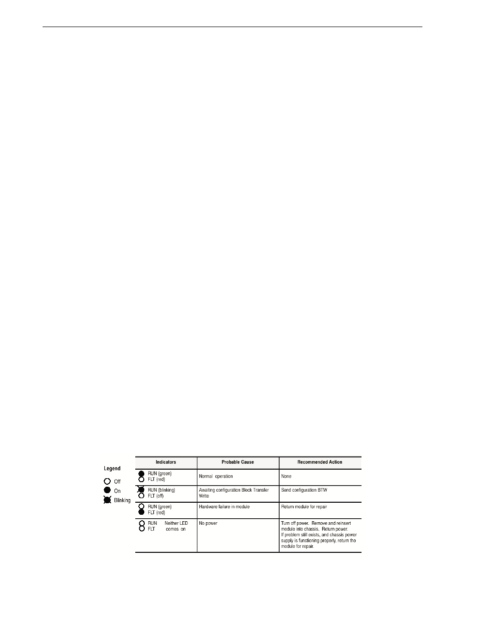
The following table lists the probable cause and recommended actions for some
common trouble indications