Spectrum Controls 1771sc-IFE32 User Manual
Page 21
Chapter 2: Installing the Input Module 11
Grounding
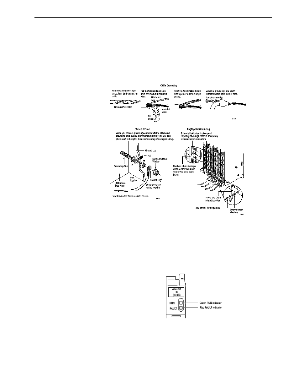
When using shielded cable wire, ground the foil shield and drain wire only at one end
of the cable. We recommend that you wrap the foil shield and drain wire together, and
connect them to a chassis mounting bolt, grounding stud or chassis single-point
grounding point (Figure 2.5). Use heat shrink tubing to seal the exit point of the wires.
At the opposite end of the cable, tape exposed shield and drain wire with electrical
tape to insulate it from electrical contact.
Indicator Lights:
The front panel of the analog input module contains a green RUN indicator and a red
FAULT indicator. At power-up an initial module self-check occurs. If there is no fault,
the red indicator turns off.
The green indicator comes on when the module is powered. It will flash until the
module is programmed. If a fault is found initially or occurs later, the red fault indica-
tor lights. Possible module fault causes and corrective action is discussed in Chapter
6, Troubleshooting.
Chapter Summary
In this chapter you learned how to install your input module in an existing program-
mable controller system and how to wire the field swing arm.