Spectrum Controls 1771sc-IFE32 User Manual
Page 12
2 PLC-5
TM
32-Channel Analog Input Module
Program Selectable Input Ranges
Valid acquisition types/ranges are listed below:
Single Ended Ranges:
Limits:
Differential Ranges:
Limits:
0*
-10 to +10 V
8
-10 to +10 V
1
0 to +10 V
9
0 to +10 V
2
0 to +5 V
10
0 to +5 V
3
+1 to +5 V
11
+1 to +5 V
4
-5 to +5 V
12
-5 to +5 V
5
0 to +20 ma
13
NA
6
+4 to +20 ma
14
NA
7
-20 to +20 ma
15
**Disabled
* = Default
** = Disabled. If this is the selected value, acquisition of this channel is disabled.
This can be used to
improve throughput in modules where some channels are not used.
NA = Not allowed.
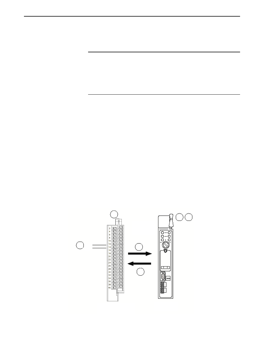
How Analog Modules
Communicate with
Programmable Controllers
The processor transfers data to the module (block transfer write) and from the module
(block transfer read) using BTW and BTR instructions in your ladder diagram
program. These instructions let the processor obtain input values and status from the
module, and let you establish the module’s mode of operation.
1. The processor transfers your configuration data to the module via a block transfer
write instruction.
2. External devices generate analog signals that are transmitted to the module
Input Module
1771sc-IFE32
I/O Chassis
Backplane
PC Processor
1
4
5
6
3
2
+_