Spectrum Controls 1771sc-IFE32 User Manual
Page 25
Chapter 3: Module Programming 15
Module Scan
Module Scan
Module Scan
Module Scan
Module Scan Time
Time
Time
Time
Time
Update time is defined as the amount of time it takes for the input module to read the
input channels and place new data into the data buffer. Scan time for your module is
shown in Appendix A.
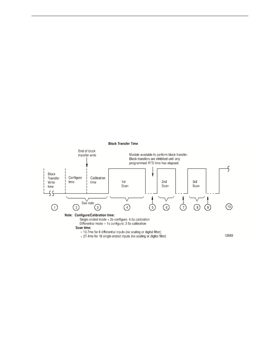
Following a block transfer write “1” the module inhibits communication until after it
has configured the data “2,” performed calibration check “3” (if requested), scanned
the inputs “4,” and filled the data buffer “5.” Write block transfers, therefore, should
only be performed when the module is being configured or calibrated.
Any time after the second scan begins “6,” a BTR request “7” can be acknowledged.
This interrupts the scan and the BTR empties the buffer. (If RTS is enabled, a BTR will
only occur after the specified time period. Refer to chapter 4.)
Following the BTR, the input module inhibits block transfer communications with the
programmable controller until it has scanned its inputs “8” and new data is ready ”9.”
The input module repeats the scan sequence “10,” updating the input values until
another block transfer request is received. Therefore, BTRs will only be completed as
frequently as the total update time of the input module.
Chapter Summary
Chapter Summary
Chapter Summary
Chapter Summary
Chapter Summary
In this chapter, you learned to program your programmable controller. You were given
a sample program for your PLC-5 processor.