Spectrum Controls 1771sc-IFE32 User Manual
Page 30
20 PLC-5
TM
32-Channel Analog Input Module
Data Format:
Data Format:
Data Format:
Data Format:
Data Format:
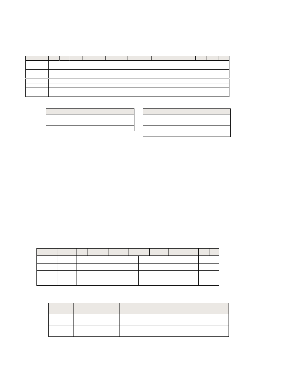
You must indicate what format will be used to read data from your module. Typically,
you select BCD with PLC-2 processors, and 2’s complement binary with PLC-3 and
PLC-5 processors. You use BTW words 8-15, bits 0-15 to set the data format.
Word/Bit
15
14
13
12
11
10
09
08
07
06
05
04
03
02
01
00
Group
8
Channel 4
Channel 3
Channel 2
Channel 1
Data Format
9
Channel 8
Channel 7
Channel 6
Channel 5
Data Format
10
Channel 12
Channel 11
Channel 10
Channel 9
Data Format
11
Channel 16
Channel 15
Channel 14
Channel 13
Data Format
12
Channel 20
Channel 19
Channel 18
Channel 17
Data Format
13
Channel 24
Channel 23
Channel 22
Channel 21
Data Format
14
Channel 28
Channel 27
Channel 26
Channel 25
Data Format
15
Channel 32
Channel 31
Channel 30
Channel 29
Data Format
Data Format:
Comment:
Data Format:
Comment:
0*
Signed 16 bit
3
Unsigned 12 bit
1
Unsigned 16 bit
4
Signed BCD
2
Signed 12 bit
5Unsigned BCD
6 through 15NA
*Within a group of 8 channels (1..8, 9..16, 17..24, or 25..32) all 8 channels must be one
of the valid voltage ranges or all 8 channels must be one of the valid current ranges.
Mixing of voltage and current sources within a group of 8 is not allowed. Also,
differential mode must be specified for two consecutive channels starting with an odd
channel (1&2, 3&4, 5&6, etc).
Input Type/Range must be configured using Binary or Hexidecimal values.
For example: Setting Word 0 to BBBB hex sets channels 1-4 to a +1 to +5V input
range.
Output is scaled to the range limits if no other scaling is applied as follows:
Digital Filtering:
Digital Filtering:
Digital Filtering:
Digital Filtering:
Digital Filtering:
The module has hardware-based high frequency filters on all channels to reduce the
effect of electrical noise on the input signal. Software digital filtering is meant to
reduce the effect of process noise on the input signal. Digital filtering is selected
using BTW words 16-19, bits 0-15.
Word/Bit 15 14 13 12 11 10 09 08 07 06 05 04 03 02 01 00
Group
16
Chan 8
Chan 7
Chan 6
Chan 5Chan 4
Chan 3
Chan 2
Chan 1
Filter Freq
17
Chan 16 Chan 15Chan 14
Chan 13
Chan 12 Chan 11 Chan 10
Chan 9
Filter Freq
18
Chan 24 Chan 23
Chan 22
Chan 21
Chan 20 Chan 19 Chan 18
Chan 17
Filter Freq
19
Chan 32 Chan 31
Chan 30
Chan 29
Chan 28 Chan 27 Chan 26
Chan 25Filter Freq
The onboard ADC data filters may be selected for the following filter frequencies:
Filter:
-3dB
Frequency:
Output Rate:
-64.5dB Frequency:
0*
13.65 Hz
350Hz
49Hz (50/60Hz rejection)
1
7.8 Hz
200 Hz
20Hz
2+
209.6 Hz
800 Hz
NA
3
1667 Hz
6400 Hz
NA
*Default
+ Filtering is set for a 1msec response, which is 800Hz for the AD7731.