Spectrum Controls 1771sc-IFE32 User Manual
Page 39
Chapter 6: Troubleshooting Your Input Module 29
Chapter 6
Troubleshooting Your Input Module
Chapter Objective:
In this chapter, we describe how to troubleshoot your module by:
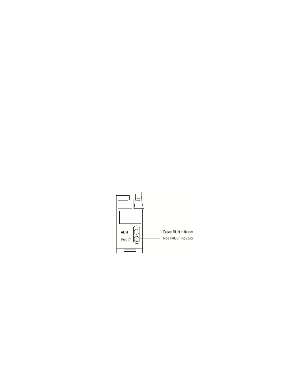
· observing the indicators
· monitoring status bits reported to the processor.
· checking module operation
· checking for common mode voltages
· isolating a bad input
Diagnostics Reported
by the Module
At power-up, the module momentarily turns on the red indicator as a lamp test, then
checks for:
· correct RAM operation
· firmware errors
Thereafter, the module lights the green RUN indicator when operating without fault,
or lights the red FAULT indicator when it detects fault conditions. The module also
reports status and specific faults (if they occur) in every transfer of data (BTR) to the
PC processor. Monitor the green and red indicators and status bits in word 1 of the
BTR file when troubleshooting your module.
Diagnostic Bits Reported
by the Analog input
Analog
In
(16 Bit)
Diagnostic bits in the read block transfer status words provide diagnostic capabili-
ties.
Word 1 provides power-up and valid data status. Words 2 and 3 provide channel
data status.
If a module on-board self-test fault occurs, block transfers will be inhibited, the red
fault (FLT) will light, and the green run (RUN) light will go out.
Word 1
Diagnostics word 1 is the first data word in the read block transfer file for transfer to
the central processor. It contains a power-up bit (bit 00) that is set (1) when the
module is first powered up. It is reset (0) after a write block transfer. It also contains