Chapter 5 module status and input data – Spectrum Controls 1771sc-IFE32 User Manual
Page 37
Chapter 5: Module Status and Input Data 27
Chapter 5
Module Status and Input Data
Chapter Objectives:
Chapter Objectives:
Chapter Objectives:
Chapter Objectives:
Chapter Objectives:
In this chapter, we describe:
· reading data from your module
· block transfer read block format
Reading Data fr
Reading Data fr
Reading Data fr
Reading Data fr
Reading Data from
om
om
om
om Y
Y
Y
Y
Your Module
our Module
our Module
our Module
our Module
Block transfer read programming moves status and data from the input module to the
processor’s data table in one I/O scan (Figure 5.1). The processor’s user program
initiates the request to transfer data from the input module to the processor.
Module input data is passed from the 1771sc-IFE32 to the PLC via a Block Transfer
Read. Two BTR formats are supported.
Bloc
Bloc
Bloc
Bloc
Block
k
k
k
k T
T
T
T
Transf
ransf
ransf
ransf
ransfer Read (BTR) Maps
er Read (BTR) Maps
er Read (BTR) Maps
er Read (BTR) Maps
er Read (BTR) Maps
Purpose:
41
Module data only
64
Module data and configuration
During normal operation, the processor transfers 41 words to the module when you
program a BTR instruction to the module’s address. When user scaling and configu-
ration echo are desired 64 words are transfered.
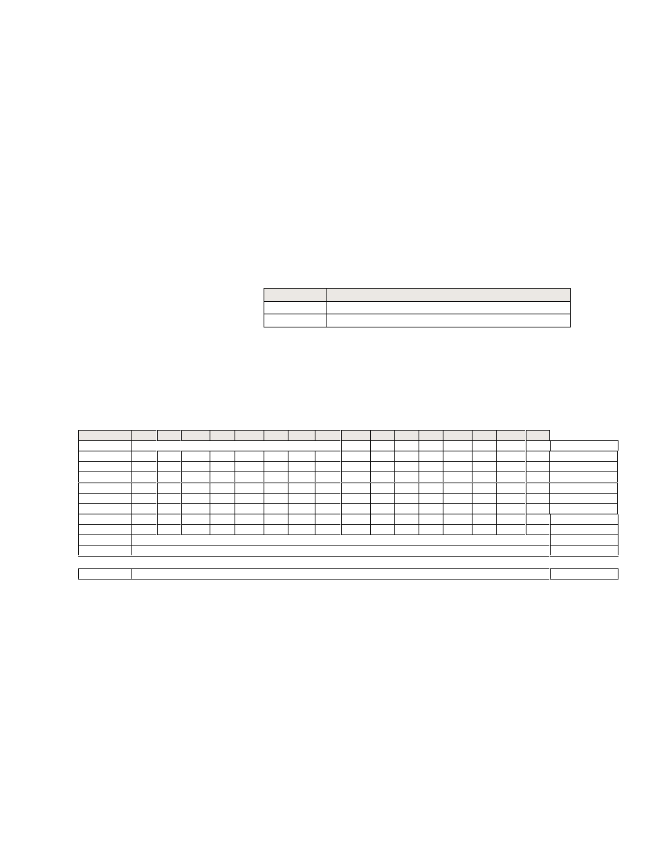
The block memory maps are shown below:
Module Data BTR
Module Data BTR
Module Data BTR
Module Data BTR
Module Data BTR
Word/Bit
15
14
13
12
11
10
09
08
07
06
05
04
03
02
01
00
0
Diagnostic Data Byte
CE
HF
EE
CS
RT
IS
OR
PU
Diagnostics
1
16
15
14
13
12
11
10
09
08
07
06
05
04
03
02
01
Channel Fault
2
32
31
30
29
28
27
26
25
24
23
22
21
20
19
18
17
Channel Fault
3
16
15
14
13
12
11
10
09
08
07
06
05
04
03
02
01
Under Range
4
32
31
30
29
28
27
26
25
24
23
22
21
20
19
18
17
Under Range
5
16
15
14
13
12
11
10
09
08
07
06
05
04
03
02
01
Over Range
5
32
31
30
29
28
27
26
25
24
23
22
21
20
19
18
17
Over Range
7
16
15
14
13
12
11
10
9
8
7
6
5
4
3
2
1
Sign
8
32
31
30
29
28
27
26
25
24
23
22
21
20
19
18
17
Sign
9
Channel 1 Data
Data
10
Channel 2 Data
Data
.
.
.
40
Channel 32 Data
Data
In differential mode every other channel is skipped. For example: Word 9 = Channel 1,
Word 11 = Channel 2, Word 13 = Channel 3...