Spectrum Controls 1771sc-IFE32 User Manual
Page 17
Chapter 2: Installing the Input Module 7
Locating the Module in
the I/O Chassis
Place your module in any I/O module slot of the I/O chassis except for the extreme left
slot. This slot is reserved for PC processors or adapter modules.
Group your modules to minimize adverse affects from radiated electrical noise and
heat. We recommend the following.
· Group analog input and low voltage dc modules away from ac modules or high
voltage dc modules to minimize electrical noise interference.
·
Do not place this module in the same I/O group with a discrete high-density I/O
module when using 2-slot addressing. This module uses a byte in both the input
and output image tables for block transfer.
Key the Backplane Connector
Place your module in any slot in the chassis except the leftmost slot, which is
reserved for processors or adapters.
ATTENTION: Observe the following precautions when inserting or removing keys:
· insert or remove keys with your fingers
· make sure that key placement is correct incorrect keying or the use of a tool can result in
damage to the backplane connector and possible system faults.
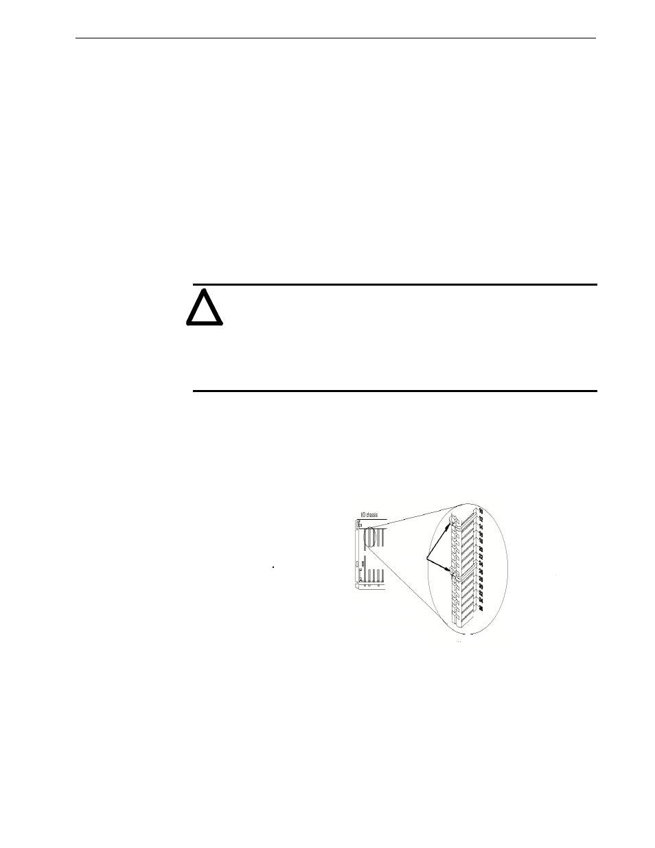
The 1771sc-IFE32 module is slitted at two places on the rear edge of the circuit board.
These slots mate with plastic keying bands which mount on the backplane connector.
Position the keying bands in the backplane connector to correspond to the key slots.
Upper Connector
ATTENTION: Insert or remove
keying bands with your fingers.
Keying Bands
Wiring Your Analog Module
Connect your I/O devices to the cat. no. 1771-WG wiring arm shipped with the
module. The wiring arm is attached to the pivot bar at the bottom of the I/O chassis. It
pivots upward and connects with the module so you can install or remove the module
without disconnecting the wires. You may also use a prewired swing arm, Allen-
Bradley part number 1492-cable[1]WN.
!