Spectrum Controls 1771sc-IFE32 User Manual
Page 19
Chapter 2: Installing the Input Module 9
immunity in typical industrial environments. Cable length for current-mode input
devices need not be as restrictive because analog signals from these devices are less
sensitive to electrical noise interference.
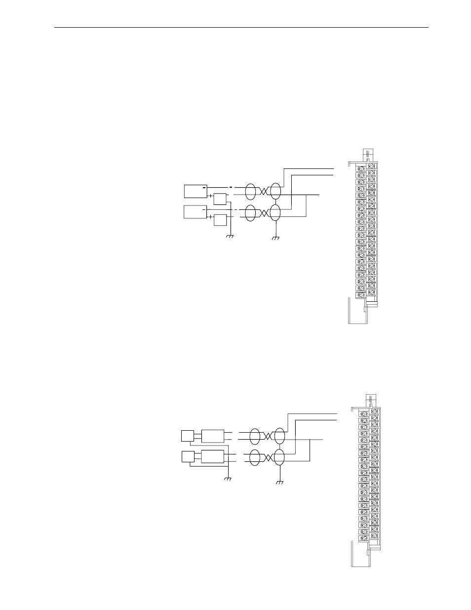
Input connections for the 1771sc-IFE32 module with single-ended and differntial
inputs are shown in the following figures.
Channel 2
Channel 4
Channel 5
Channel 7
Common Group 1
Channel 10
Channel 12
Channel 13
Channel 15
Common Group 2
Channel 18
Channel 20
Channel 21
Channel 23
Common Group 3
Channel 26
Channel 28
Channel 29
Channel 31
Common Group 4
Channel 1
Channel 3
Common Group 1
Channel 6
Channel 8
Channel 9
Channel 11
Common Group 2
Channel 14
Channel 16
Channel 17
Channel 19
Common Group 3
Channel 22
Channel 24
Channel 25
Channel 27
Common Group 4
Channel 30
Channel 32
+
-
+
-
2-Wire
Transmitter
2-Wire
Transmitter
Power
Supply
Power
Supply
Source Ground
Connection Diagram for 32 Single-ended
Inputs and Two-wire Transmitters
Commons are tied in groups of four inside the module. Jumper all
unused channels to appropriate group common to reduce noise.
Tie power supply grounds together to minimize ground loops.
Attention: This signle includes any common mode voltage
present between either input terminal and module common.
If an input exceeds this range channel-to-channel cross talk
can cause invalid input readings and invalid under or over range
readings.
The sensor cable must be shielded. The shield must extend
the length of the cable to the point of termination.
Channel 2
Channel 4
Channel 5
Channel 7
Common Group 1
Channel 10
Channel 12
Channel 13
Channel 15
Common Group 2
Channel 18
Channel 20
Channel 21
Channel 23
Common Group 3
Channel 26
Channel 28
Channel 29
Channel 31
Common Group 4
Channel 1
Channel 3
Common Group 1
Channel 6
Channel 8
Channel 9
Channel 11
Common Group 2
Channel 14
Channel 16
Channel 17
Channel 19
Common Group 3
Channel 22
Channel 24
Channel 25
Channel 27
Common Group 4
Channel 30
Channel 32
+
-
+
-
Source Ground
Connection Diagram for 32 Single-ended
Inputs and Four-wire Transmitters
Commons are tied in groups of four inside the module. Jumper all
unused channels to appropriate group common to reduce noise.
Tie power supply grounds together to minimize ground loops.
Attention: This signle includes any common mode voltage
present between either input terminal and module common.
If an input exceeds this range channel-to-channel cross talk
can cause invalid input readings and invalid under or over range
readings.
The sensor cable must be shielded. The shield must extend
the length of the cable to the point of termination.
4-Wire
Transmitter
4-Wire
Transmitter
Power
Supply
Power
Supply