Spectrum Controls 1771sc-IFE32 User Manual
Page 31
Chapter 4: Configuring Your Module 21
Channel Update times based on filter frequency are listed below.
Filter
1 Channel
16 Channels
32 Channels
7.8 Hz
120 ms
1920 ms
3840 ms
13.65 Hz
67.8 ms
1085 ms
2170 ms
209.6 Hz
5.4 ms
86.5 ms
173 ms
1667 Hz
2.1 ms
33.6 ms
67.2 ms
Automatic System Calibration
Automatic System Calibration
Automatic System Calibration
Automatic System Calibration
Automatic System Calibration
(Autocal)
(Autocal)
(Autocal)
(Autocal)
(Autocal)
The built in capability of the Analog to Digital Converter to perform system calibra-
tions may be performed at a rate defined by the user. The exact time of system
calibration can not be specified, only the rate at which is performed.
Word/Bit
15
14
13
12
11
10
09
08
07
06
05
04
03
02
01
00
Group
20
Automatic Calibration Rate
Autocal
The table below illustrates the configuration options using Configuration Word 20.
AutoCal:
Rate:
0*
Once every 30 minutes.
1
Once an hour.
2
Once a day.
3
On command.
4
Once on power on/reset only.
* -Default
Flags
Flags
Flags
Flags
Flags
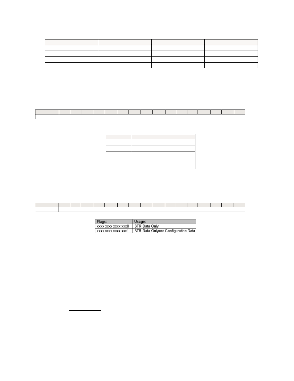
The user may specify the Block Transfer Read size using Configuration Word 21.
Word/Bit
15
14
13
12
11
10
09
08
07
06
05
04
03
02
01
00
Group
21
Debug Flags
Debug Flags
Settings are as follows:
0
PU
1 = Power up complete
1
OR*
1 = Out of range error occurred
2
IS
1 = Invalid scaling detected
3
RTS
1 = Real time sampling BTR timeout
4
CS*
1 = Calibration status
5
EE
1 = EEPROM valid
6
HF
1 = Hardware fault
7
CE*
1 = Configuration Error
* Channel faults. Channels 1 – 32 (1 to 20hex) loaded in diagnostics data.
If configuration error and 0 in diagnostics data, RTS or autocal values are invalid.
Power up complete
This bit is set when the power up test is complete, no hardware failures were de-
tected, and the module is ready to start processing block transfer write requests and/