Data words for floating point rate mode, Setting the rate limit / r factor, Input registers: channel data – Spectrum Controls 1746sc-CTR4 User Manual
Page 61
Appendix A: Floating Point Rate Mode
61
Setting the Rate Limit / R
Factor:
The R Factor function is used to activate the floating point mode. Setting
the value to -1 activates this mode. Use Bit 15 in your channel
configuration word to save the R factor in the modules non-volatile
memory.
Figure A.3 - Rate Limit / R Factor Word
15
0
Address
Rate Limit / R Factor
O:e.z
9
8
Input Registers:
Channel Data
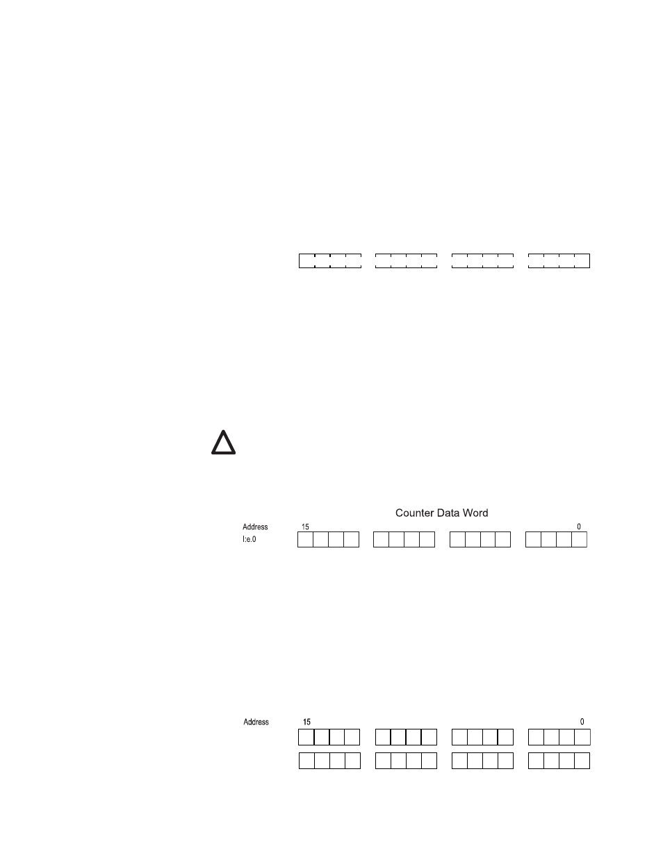
Counter Output Register, Low word:
This output data register contains the lower word of the counter
accumulator. This register is a signed 16 bit word in binary 2’s
complement format and will allow count values up to ±32K. This word is
used in conjunction with the counter’s upper output word when in the
extended count mode. Bit 15 represents the sign for each word.
Note: Extended count mode is not a valid configuration when using the
floating point rate mode.
Figure 4.10 -Counter Low Word
8
9
Counter Input Low
Rate Output Register words:
These two output data registers contain the rate value while operating in
floating point rate mode. The registers represent a 32 bit word in binary
2’s complement format and when combined form the 32 bit floating point
rate value.
Figure 4.12 -Counter Rate Word
8
9
I:e.x
I:e.y
Rate Output Low
Rate Output High
Data Words for Floating Point Rate Mode
!