Spectrum Controls 1746sc-CTR4 User Manual
Page 53
Chapter 6: Testing Your Module
53
Interpreting The LED
Indicators
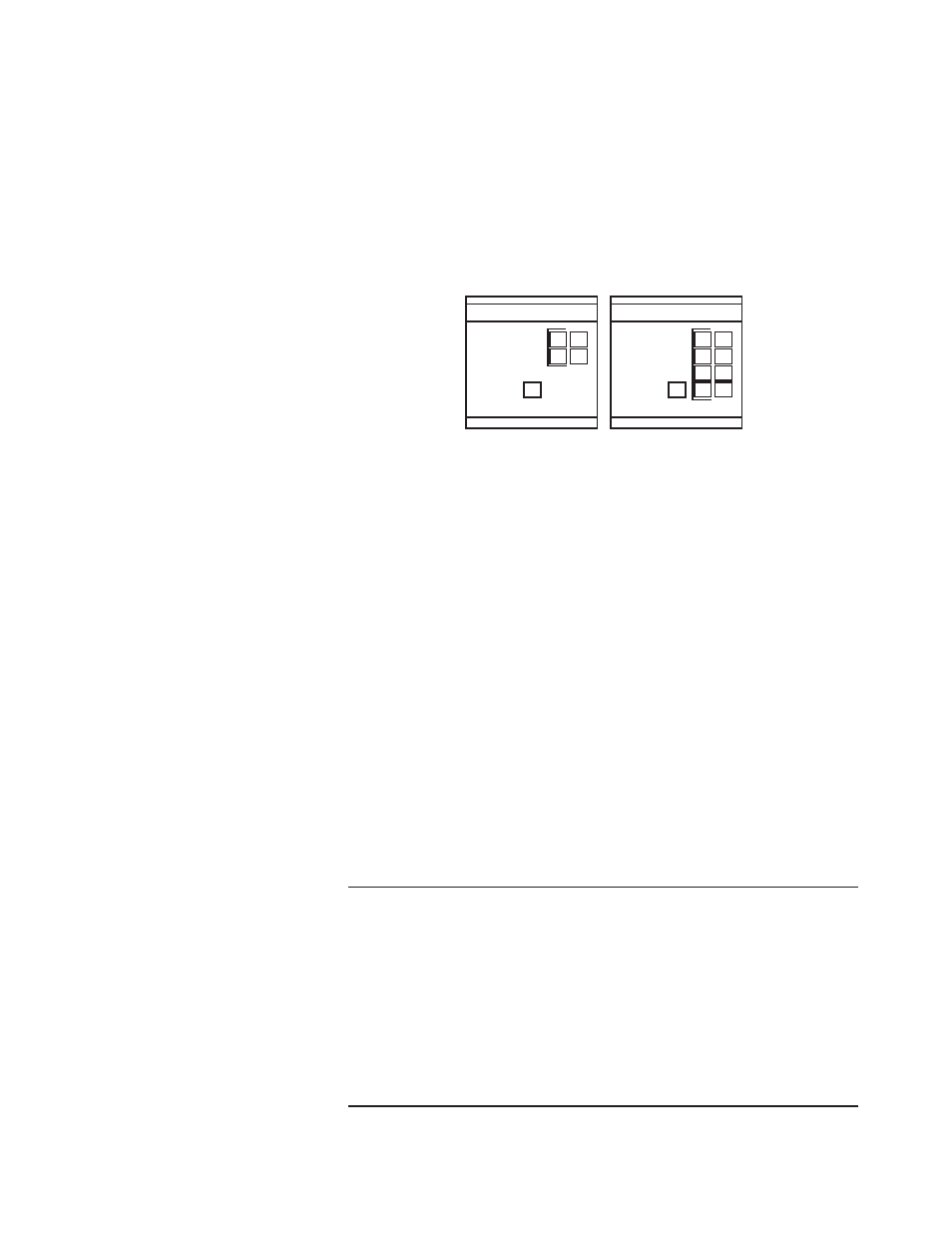
Your module has nine LEDs: eight channel status LEDs (numbered 0–7
for channels 0–7, respectively) and one module status LED.
Figure 6.1. LED block
CTR8
INPUT
MODULE
CHANNEL
STATUS
0 4
1 5
2 6
3 7
CTR4
INPUT
MODULE
CHANNEL
STATUS
0 2
1 3
Operation
The module has 9 (5-CTR4) LED’s that indicate the following…
Module Status LED:
1 Green LED
Indicates that the module has
completed its self test and is ready. Module
and self test errors are reported by an error
blink code.
Channel Status LED’s:
8 Green LEDs The channel status LED’s
indicate that the given channel is Enabled.
See table below for blink code.
The Module and Channel Status LEDs produce diagnostic blink codes
when an error occurs. If the Module Status LED produces a blink code,
please contact your local AB Representative or one of our technical
support engineers
The Channel Status LED error codes may be used to detect channel
configuration errors.
T
TT
T
Taaaaabbbbble 6.1 Channel Sta
le 6.1 Channel Sta
le 6.1 Channel Sta
le 6.1 Channel Sta
le 6.1 Channel Status LED Blink Codes
tus LED Blink Codes
tus LED Blink Codes
tus LED Blink Codes
tus LED Blink Codes
Blink #
Blink #
Blink #
Blink #
Blink # Fault
Fault
Fault
Fault
Fault
1
Frequency Scale / F Factor Out of Range
2
Frequency Input Range Mismatch
Channel pairs,0-1 / 2-3 / 4-5 / 6-7 must be configured for the same range.
3
Bidirectional or Quadrature Mode Configuration Error
Channel pair configuration word must be identical for these modes.
4
Negative K, M, or F Factor.
5
Limit out of range.
6
Preset out of range.
7
High resolution rate and 24 bit counter mode set.