Spectrum Controls 1746sc-CTR4 User Manual
Page 37
Chapter 4: Channel Configuration, Data, and Status
37
Input Registers -
Channel Data
The channel data consists of 4 words, the lower counter data value, the
upper counter data value, the rate data value and the channel status data.
Table 4.4 - Data Word Addresses
CTR8
CTR4
Scale/Limit Value
I:e.0 to I:e.3
I:e.0 to I:e.3
0 Channel MSW, LSW, Rate Data, Status Reg
I:e.4 to I:e.7
I:e.4 to I:e.7
1 Channel MSW, LSW, Rate Data, Status Reg
I:e.8 to I:e.11
I:e.8 to I:e.11
2 Channel MSW, LSW, Rate Data, Status Reg
I:e.12 to I:e.15
I:e.12 to I:e.15
3 Channel MSW, LSW, Rate Data, Status Reg
I:e.16 to I:e.19
(n/a)
4 Channel MSW, LSW, Rate Data, Status Reg
I:e.20 to I:e.23
(n/a)
5 Channel MSW, LSW, Rate Data, Status Reg
I:e.24 to I:e.27
(n/a)
6 Channel MSW, LSW, Rate Data, Status Reg
I:e.28 to I:e.31
(n/a)
7 Channel MSW, LSW, Rate Data, Status Reg
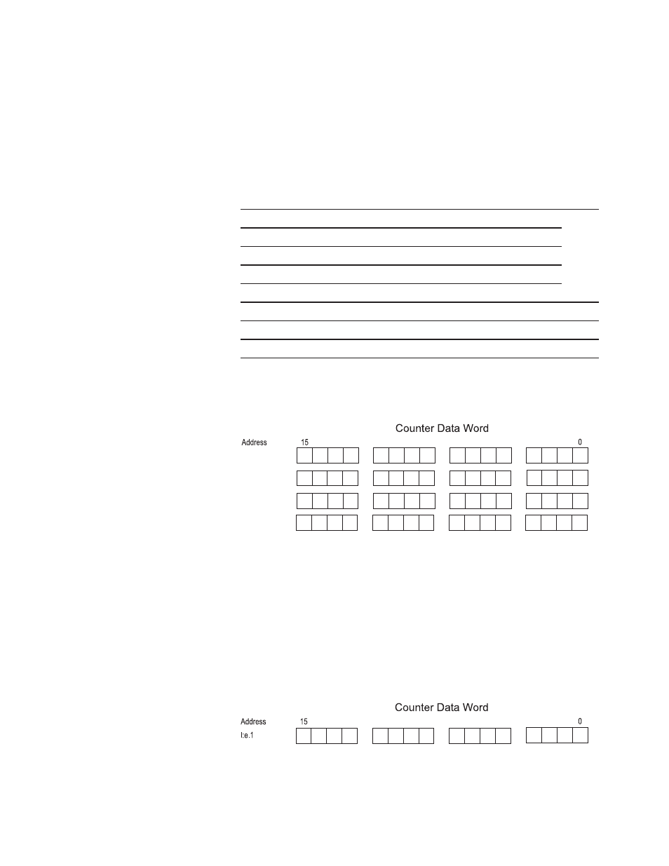
Figure 4.9 - Data Words
8
9
I:e.w
I:e.x
I:e.y
I:e.z
Rate Output
Counter MSW
Counter LSW
Status Output
Counter Output Register, High word:
This output data register contains the upper word of the counters
accumulator. This register is a 16 bit word in binary 2’s complement
format. When operating in the extended count mode, ±8M counts, the
high word is equal to the counter value/1,000 and the low word is the
remainder. For example, a count of 40,123 would result in a high word
equal to 40, and the low word equal to 123. The high word = 40 and the
low word = 123.
Figure 4.11 -Counter High Word
8
9
Counter Input High
This register is always zero when operating the the standard (32k) count
mode.