Programming / application examples, Chapter 5 – Spectrum Controls 1746sc-CTR4 User Manual
Page 43
Programming / Application Examples
Learning to configure your counter to meet your application requirements
will require knowledge of counter configuration, ladder logic programming
and data management. Read this chapter to familiarize yourself with how
to use the advanced features of your module for:
Sample Counter
Configuration
Simple Linear
Counter
(10,000 Limit):
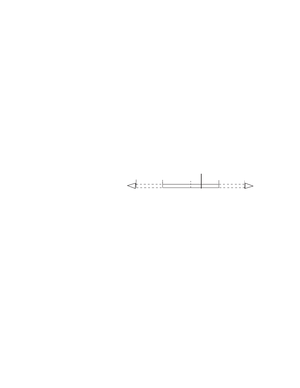
This configuration for Channel 0 of the counter module will allow the user
to count from zero to a maximum value of 10,000 counts.
0
+32K
-32K
-8M
-8M
10,000
To facilitate this you must input a Limit of 10,000 counts. This cycle will
continue, without stopping , with these configuration settings.
Channel 0 - Output Register Configuration (O:e.0)
Output Register Configuration
Config. Bit
Description
Bit Setting
Description
*15
Normal
0
Normal Mode
14
Roll Under
0
Roll to Neg. #s
13
Roll Over
1
Roll to Preset
12
Direction
0 (Default)
No Inversion
11
Count Size
0 (Default)
±32K Std.
10
Freq. Filter
0 (Default)
50kHz
9
Stop on Limit
0 (Default)
No Stop
8
Stop on Zero
0 (Default)
No Stop
6/7
Count Mode
00 (Default)
Unidirectional
4/5
Input Range
00 (Default)
50mV-30VAC
3
Rate. Mode
0 (Default)
Instant Mode
2
Reset Flags
0 (Default)
Off
1
Counter Preset 0 (Default)
Off
No scale factors or associated flags are used. The input range is based on
your input signal type. The filter on the input rate defaulted to 50kHz.
Configuration Word
O:e.2
Counter Limit
10,000
We have set the limit to 10,000.
Chapter
5