Spectrum Controls 1746sc-CTR4 User Manual
Page 38
38
SLC 500
™
50 KHz Counter / Flowmeter Module
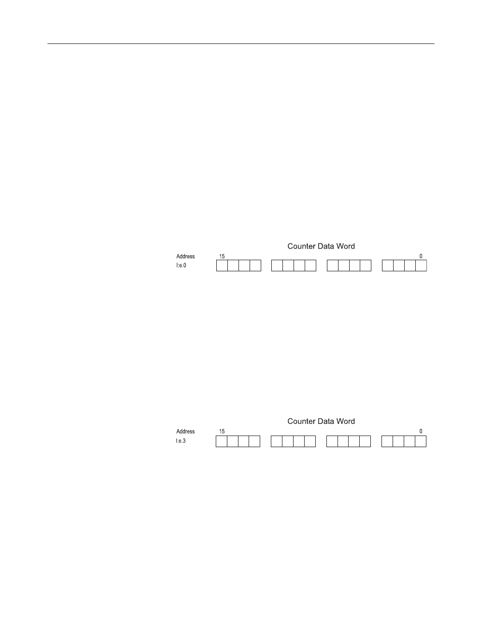
Counter Output Register, Low word:
This output data register contains the lower word of the counter
accumulator. This register is a signed16 bit word in binary 2’s complement
format and will allow count values up to ±32K. This word is used in
conjunction with the counter’s upper output word when in the extended
count mode. Bit 15 represents the sign for each word. When the counter
is operating in the extended mode, the low and high words are used
together to form a composite number that extends the counter to ±8M.
The low word represents counts up to 1000 and the high word represents
counts that carry over 1000. (When the counter is configured in Extended
mode.)
Actual count = (Value of the high word x 1000) + (Value of the low word).
Figure 4.10 -Counter Low Word
8
9
Counter Input Low
Rate Output Register word:
Refer to Appendix A for floating point rate mode.
This output data register contains the rate value while operating in rate
mode. This register is a 16 bit word in binary 2’s complement format and
represents the input value. Note that if the R Factor is present the output
date value is represented as the Rate / R Factor. Rates greater than
32kHz must use a R factor otherwise overflow will occur. If the R factor
is set to 2 and your input rate is 50kHz, the data output word will read
25,000.
Figure 4.12 -Counter Rate Word
8
9
Rate Input Value