Spectrum Controls 1746sc-CTR4 User Manual
Page 17
Chapter 2: Installing And Wiring Your Module
17
To guard against electrostatic damage and improve chassis grounding,
connect one of the shield pins on the terminal block of your module to
the chassis itself.
7. Repeat steps 1 through 6 for each channel on your module.
A system may malfunction due to a change in its operating environment.
After installing and wiring your module, check system operation. See the
Allen-Bradley system Installation and Operation Manual for more
information.
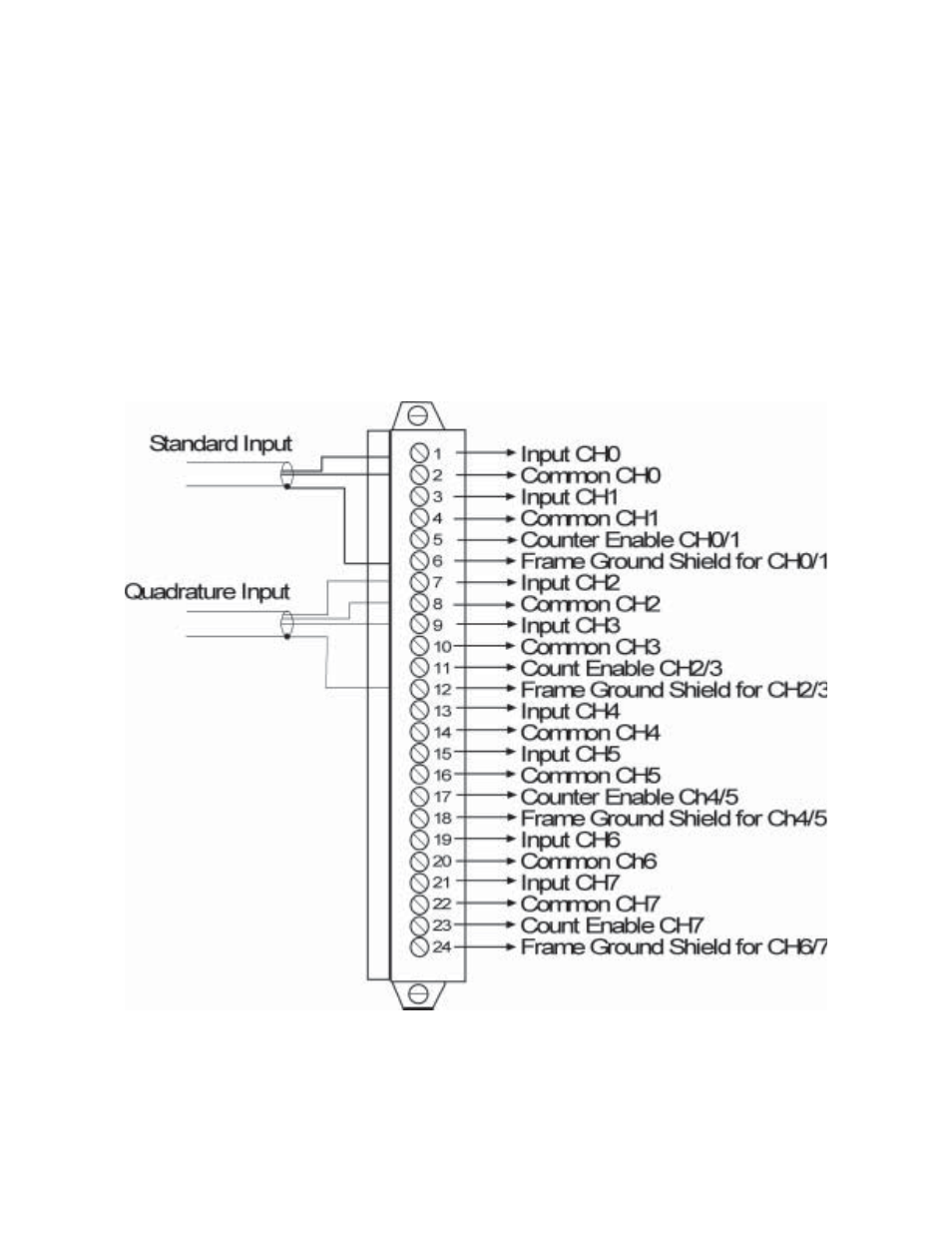
Terminal Block Wiring
Note: Channels 4-7 are only available on the 1746sc-CTR8 module.
Note: A pull up resistor may be necessary for open collector inputs. Refer
to Chapter 6 for additional information.