Ctr-8, Ctr-4, Module addressing – Spectrum Controls 1746sc-CTR4 User Manual
Page 20: 50 khz counter / flowmeter input module
20
SLC 500
™
50 KHz Counter / Flowmeter Input Module
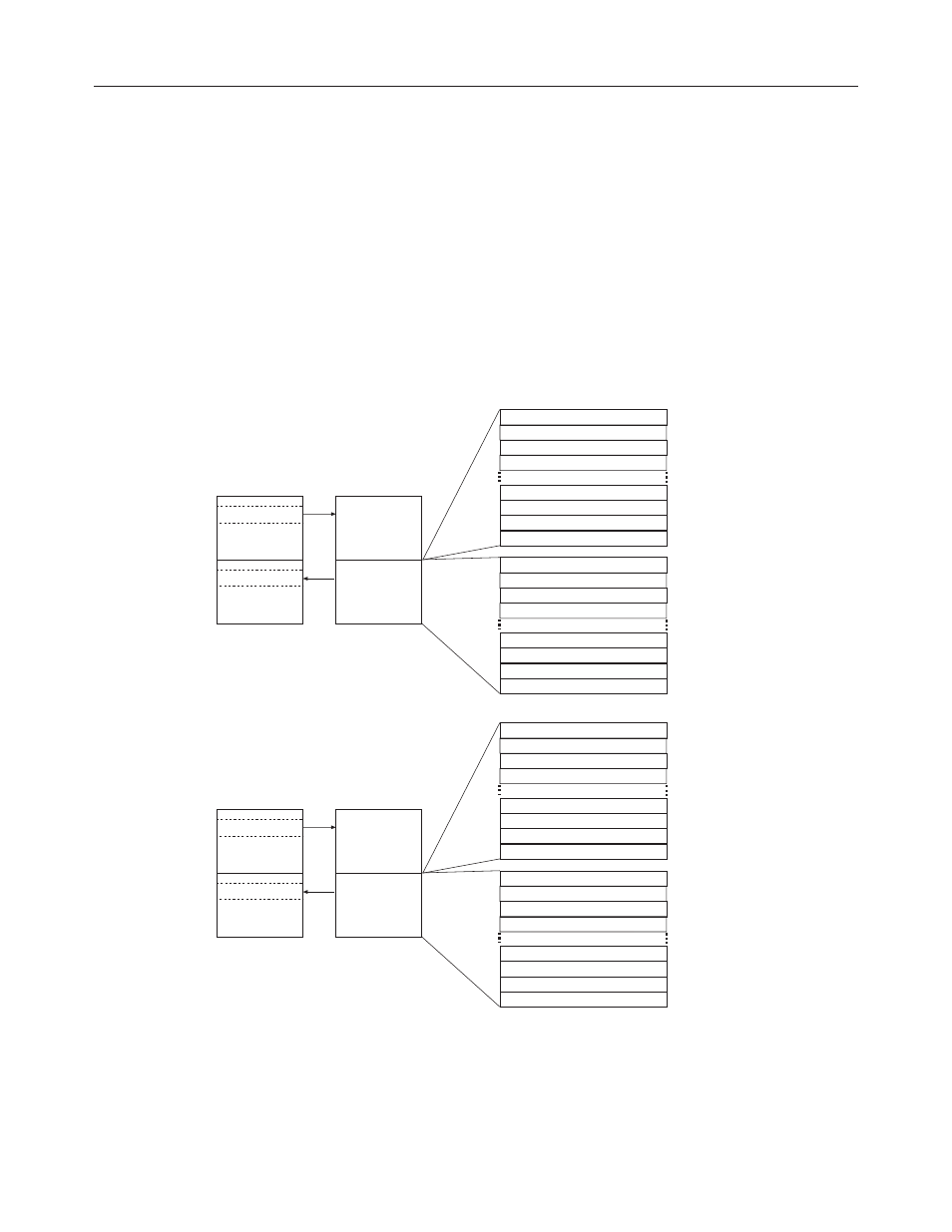
Module Addressing
The CTR-8 module uses 32 input and 32 output registers, and the CTR-4
module uses 16 input and 16 output registers. Both modules use Class
III mode operation and cannot be used with Class I operation. The
following memory map shows you how the SLC processor’s output and
input tables are defined for the module. The SLC 5/01 processor does
not support Class III operation and is not compatible with this module.
This module is not suitable for use in remote rack applications with ASB
modules due to the input / output word size.
Figure 3.1Image table
Input
Scan
Output
Scan
Output Image
Slot e
Input Image
Slot e
SLC 5/02-05
Data Files
Output Image
32 Words
Counter
Module
Image Table
Input Image
32 Words
CTR-8
Channel 0 Configuration Word
Channel 0 Preset / M Factor
Channel 0 Limit / K Factor
Channel 0 Rate Lim / R Factor
Bit 0 Address
Word 29
O:e.29
Word 30
O:e.30
Word 31
O:e.31
Word 0
O:e.0
Word 1
O:e.1
Word 2
O:e.2
Bit 15
Word 3
O:e.3
Word 28
O:e.28
Channel 7 Configuration Word
Channel 7 Preset / M Factor
Channel 7 Limit / K Factor
Channel 7 Rate Lim / R Factor
Channel 0 Output Low (MSW)
Channel 0 Output High (LSW)
Channel 0 Frequency
Channel 0 Status Word
Bit 0 Address
Word 29
I:e.29
Word 30
I:e.30
Word 31
I:e.31
Word 0
I:e.0
Word 1
I:e.1
Word 2
I:e.2
Bit 15
Word 3
I:e.3
Word 28
I:e.28
Channel 7 Output Low (MSW)
Channel 7 Output High (LSW)
Channel 7 Frequency
Channel 7 Status Word
Input
Scan
Output
Scan
Output Image
Slot e
Input Image
Slot e
SLC 5/02-05
Data Files
Output Image
16 Words
Counter
Module
Image Table
Input Image
16 Words
CTR-4
Channel 0 Configuration Word
Channel 0 Preset / M Factor
Channel 0 Limit / K Factor
Channel 0 Rate Lim / R Factor
Bit 0 Address
Word 13
O:e.13
Word 14
O:e.14
Word 15
O:e.15
Word 0
O:e.0
Word 1
O:e.1
Word 2
O:e.2
Bit 15
Word 3
O:e.3
Word 12
O:e.12
Channel 3 Configuration Word
Channel 3 Preset / M Factor
Channel 3 Limit / K Factor
Channel 3 Rate Lim / R Factor
Channel 0 Output Low (MSW)
Channel 0 Output High (LSW)
Channel 0 Frequency
Channel 0 Status Word
Bit 0 Address
Word 13
I:e.13
Word 14
I:e.14
Word 15
I:e.15
Word 0
I:e.0
Word 1
I:e.1
Word 2
I:e.2
Bit 15
Word 3
I:e.3
Word 12
I:e.12
Channel 3 Output Low (MSW)
Channel 3 Output High (LSW)
Channel 3 Frequency
Channel 3 Status Word