2nd step: make the electrical connection, Vertical installation, Additional install steps for “dual seal” units – SOR 815DT Smart User Manual
Page 2
2/24
Form 1588 (09.14) ©SOR Inc.
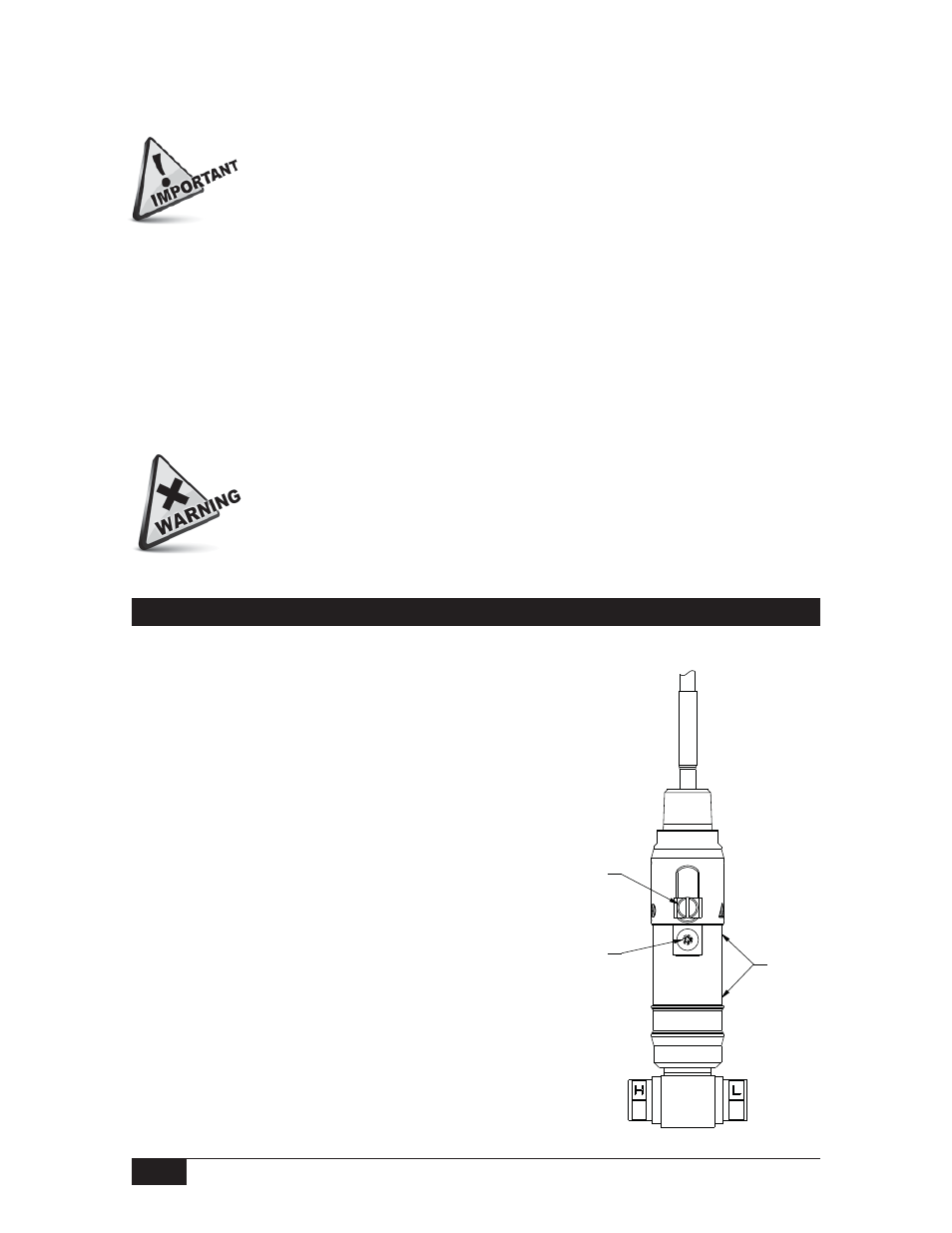
NAMEPLATE
AREA
EXTERNAL
GROUND
PROVISION
SET SCREW
ANNUNCIATION
PATH
2nd Step: Make the Electrical Connection
The electrical connection may be installed on an adequately supported rigid conduit
system. Use suitable locknuts (not provided) when mounting the instrument to an
unthreaded (knockout) hole.
Securely connect the conduit pipe or fitting by holding the flats on the electrical
connection while tightening.
Electrical connection may be rigid or flexible conduit.
Unit in Hazardous Locations - Prior to removal from service, make sure that the
work area is declassifi ed. Failure to do so could result in severe personal injury
or substantial property damage.
Failure to follow these additional installation instructions may
diminish the “Ingress Protection” and “NEMA” ratings of the “Dual
Seal” instruments. An improper installation will void the warranty.
Vertical Installation
The figure on the right depicts the vertical installation
profile; with the electrical leads on top. The
instrument may be installed with the electrical
leads on the bottom.
The nameplate (tag) should cover the set screw
(annunciation path). Position the nameplate
slot opposite the set screw; i.e., the nameplate
slot should be located 180° from the set screw.
Additional Install Steps for “Dual Seal” Units
Do not exceed 1,000 psi of static pressure.
NOTE: The high pressure side (stamped H) and the low pressure side (stamped L) have 1/4”
NPT(F) process connections as standard.
NOTE: This product should be installed by trained and competent personnel only.
Drawing
0091555