Delta Electronics AC Motor Drive VFD-XXXM User Manual
Page 3
English-3
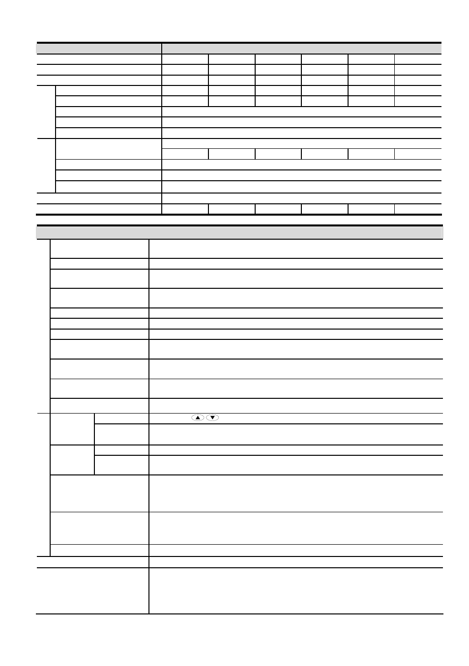
Voltage Class
575V Class
Model
Number
VFD-XXXM
007 015 022 037 055 075
Max. Applicable Motor Output (kW)
0.75
1.5
2.2
3.7
5.5
7.5
Max.
Applicable
Motor
Output
(hp)
1.0 2.0 3.0 5.0 7.5 10
Rated
Output
Capacity
(kVA)
1.7 3.0 4.2 6.6 9.9 12.2
Rated
Output
Current
(A) 1.7 3.0 4.2 6.6 9.9 12.2
Maximum Output Voltage (V)
3-phase Proportional to Input Voltage
Output Frequency (Hz)
0.1~400 Hz
Outp
ut Rati
ng
Carrier Frequency (kHz)
1-10
3-phase
Rated Input Current (A)
2.4 4.2 5.9 7.0 10.5 12.9
Rated Voltage, Frequency
3-phase 500~600 VAC, 50/60Hz
Voltage Tolerance
-15%~+10% (425~660 VAC)
Inpu
t Ratin
g
Frequency Tolerance
±
5% (47~63 Hz)
Cooling Method
Fan Cooled
Weight
(kg)
1.5 1.5 2.0 3.2 3.2 3.3
General Specifications
Control System
SPWM (Sinusoidal Pulse Width Modulation) control (V/F or sensorless vector
control)
Freq. Setting Resolution
0.1Hz
Output Frequency
Resolution
0.1Hz
Torque Characteristics
Including the auto-torque, auto-slip compensation; starting torque can be 150% at
5.0Hz
Overload Endurance
150% of rated current for 1 minute
Skip Frequency
Three zones, settings range 0.1-400Hz
Accel/Decel Time
0.1 to 600 seconds (4 Independent settings for Accel/Decel Time)
Stall Prevention Level
Frequency Setting
20 to 200%, Setting of Rated Current
DC Injection Braking
Operation frequency 0-60Hz, output 0-100% rated current
Start time 0-5 seconds, stop time 0-25 seconds
Braking Torque
Approx. 20% (up to 125% possible with option brake resistor or brake unit
externally mounted, 1-15HP braking transistor built-in)
C
ontr
o
l C
h
ar
acter
isti
cs
V/F Pattern
Adjustable V/F pattern
Keypad Setting
by
Frequency
Setting
External
Signal
Potentiometer-5K
Ω/0.5W, 0 to +10VDC, 4 to 20mA RS-485 interface; Multi-
Function Inputs 0 to 5 (7 steps, Jog, up/down)
Keypad
Set by RUN, STOP
Operation
Setting
Signal
External
Signal
M0 to M5 can be combined to offer various modes of operation, RS-485 serial
interface (MODBUS).
Multi-Function Input Signal
Multi-step selection 0 to 7, Jog, accel/decel inhibit, first to forth accel/decel
switches, counter, PLC operation, external Base Block (NC, NO), auxiliary motor
control is invalid, selections, driver reset, UP/DOWN key settings, sink/source
selection
Multi-Function Output
Indication
AC drive operating, frequency attained, non-zero, base block, fault indication,
local/remote indication, PLC operation indication, auxiliary motor output, driver is
ready, overheat alarm, emergency stop
Oper
ati
ng C
har
acter
ist
ics
Analog Output Signal
Analog frequency/current signal output.
Alarm Output Contact
1 Form C contact or open collector output
Operation Functions
AVR, S-Curve, over-voltage, over-current stall prevention, fault records, adjustable
carrier frequency, DC braking, momentary power loss restart, auto tuning,
frequency limits, parameter Lock/Reset, vector control, counter, PID Control, PLC,
MODBUS communication, reverse Inhibition, abnormal reset, abnormal re-start,
digital frequency output, sleep/revival function, 1st/2nd frequency source selections