LINK Systems OmniLink - Feed Interface User Manual
Page 21
OmniLink 5000 Feed Manual
December 13, 1999
2.15
Manual Rev 2.3
2.20
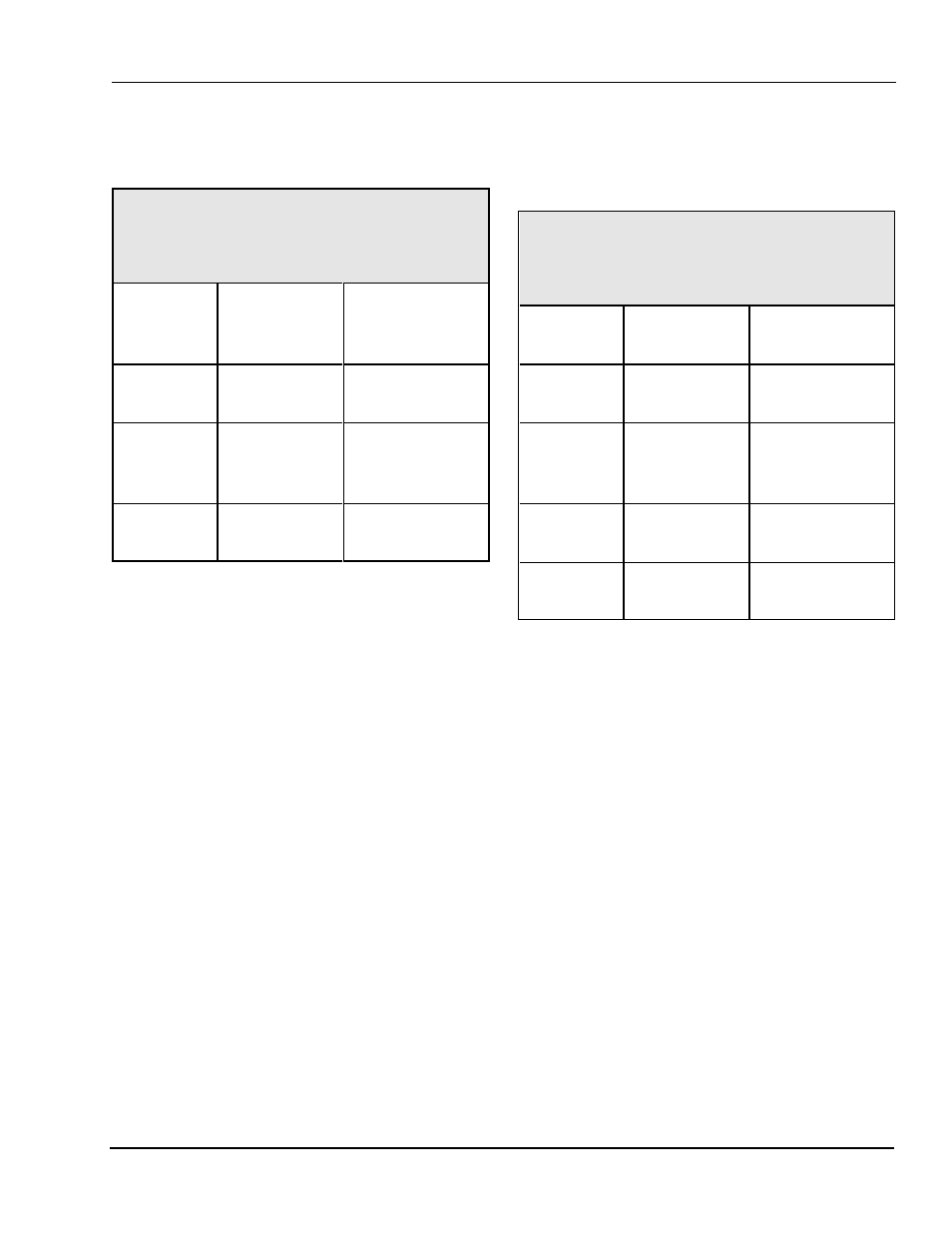
Unico Interface
The connection to a Unico Feed is as follows:
Table 2.21
Unico Connections
Link PN 106746
OmniLink
Feed Port
Function /
Color
Unico Comm
Board 25 Pin
232 Connector
Pin 1
(GND)
Ground
(WHITE)
Pin 7 (GND)
Pin 2
(RXD)
Receive data
from feed
(BLACK)
Pin 2 (TXD)
Pin 3
(TXD)
Transmit data
to feed (RED)
Pin 3 (RXD)
Notes:
Pins 4 and 5 on the Unico 232 communications
connector must be tied together (RTS to CTS).
There are two different operating systems in use
on Unico feeds. The System 5000 supports
these as “Type 1" and “Type 2" Unico feeds.
You may have to experiment to find out which
type you have.
2.21
Waddington Interface (MC500
Controller)
The connection to a Waddington Feed is as follows:
Table 2.22
Waddington Connections
Link PN 106748
OmniLink
Feed Port
Function /
Color
Waddington
Connector J5
Pin 1
(GND)
Ground
(WHITE)
Pin 7
Pin 2
(RXD)
Receive data
from feed
(BLACK)
Pin 3
Pin 3
(TXD)
Transmit data
to feed (RED)
Pin 2
No
Connect
Shield
Pin 1
Notes:
The communication port of the Waddington
Feed Controller must be set to 9600 baud (see
Waddington manual).