LINK Systems OmniLink - Feed Interface User Manual
Page 17
OmniLink 5000 Feed Manual
December 13, 1999
2.11
Manual Rev 2.3
2.16
Indramat CLM Version 1.2 Interface
This is an older version of Indramat firmware.
Connections to the Indramat CLM are as follows:
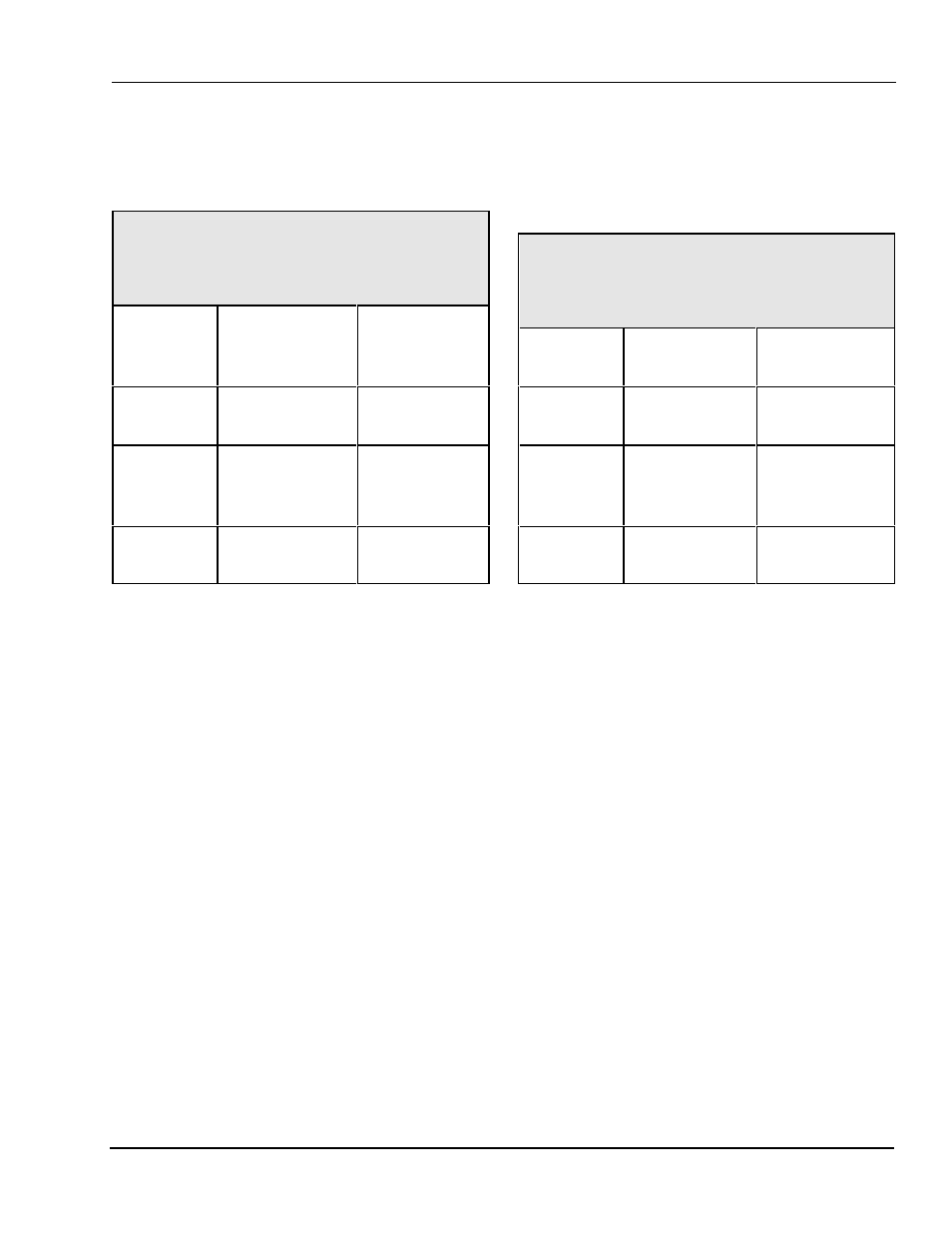
Table 2.15
Indramat CLM Servo Connections
Link PN 106739
OmniLink
Feed Port
Function /
Color
Indramat
CLM
Connector X6
Pin 1
(GND)
Ground
(WHITE)
Pin 7
Pin 2
(RXD)
Receive data
from feed
(BLACK)
Pin 2
Pin 3
(TXD)
Transmit data
to feed (RED)
Pin 3
Notes:
Not Supported on old communications board.
For new communication board, the following
Parameter Values must be set up at the CLM:
a) B102 = 0.
b) Feed port baud rate, data bits, and stop bits
must be set at the OmniLink OIT the same
as the CLM.
2.17
Indramat SOT with CLM Version 1.2
Interface.
This is an older version of Indramat firmware.
Connections to the Indramat SOT are as follows:
Table 2.16
Indramat SOT Connections
Link PN 106738
OmniLink
Feed Port
Function /
Color
Indramat SOT
Connector X3
Pin 1
(GND)
Ground
(WHITE)
Pin 7
Pin 2
(RXD)
Receive data
from feed
(BLACK)
Pin 2
Pin 3
(TXD)
Transmit data
to feed (RED)
Pin 3
Notes:
Not supported on old communications board.
For new communication board, the following
Parameter Values must be set up at the CLM:
a) B102 = 0.
The SOT should be connected to the CLM as
shown in the Indramat manuals. Once the SOT
operation is verified, serial port 2 must be
configured and “Relay Mode” must be enabled
for the OmniLink 5000 to pass commands to the
CLM through the SOT.
a) Press
b) Enter the password “SOT” when prompted.
c) Select “SOT Parameters” from the menu.
d) Select “Configure Port 2" from the menu.
e) Set baud rate to 9600, parity to None, data
bits to 8, and stop bits to 1.
f) Go back to the first menu (the on with “SOT
parameters”).