LINK Systems OmniLink - Feed Interface User Manual
Page 15
OmniLink 5000 Feed Manual
December 13, 1999
2.9
Manual Rev 2.3
2.13
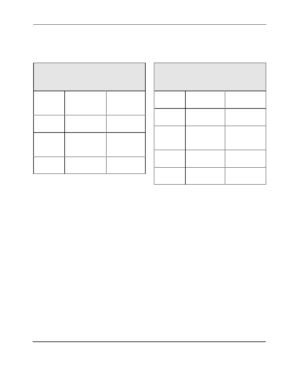
Indramat CLM Interface
Connections to the Indramat CLM are as
follows:
Table 2.12
Indramat CLM Servo Connections
Link PN 106739
OmniLink
Feed Port
Function /
Color
Indramat
CLM
Connector X6
Pin 1
(GND)
Ground
(WHITE)
Pin 7
Pin 2
(RXD)
Receive data
from feed
(BLACK)
Pin 2
Pin 3
(TXD)
Transmit data
to feed (RED)
Pin 3
Notes:
For old communication board only, the
following Parameter Values must be set up at
the CLM:
a) A100 = 3.
b) B102 = 0.
c) B118 = 1 00 0.
d) B119 = 9600 8 1 02.
For new communication board only, the
following Parameter Values must be set up at
the CLM:
a) B102 = 0.
b) B118 first number must not be 0.
c) Feed port baud rate, data bits, and stop bits
must be set at the OmniLink OIT the same
as the CLM.
2.14
Indramat DLC Interface
Connections to the Indramat DLC are as
follows:
Table 2.13
Indramat DLC Servo Connections
Link PN 106744
OmniLink
Feed Port
Function /
Color
Indramat DLC
Connector X31
Pin 1
(GND)
Ground
(WHITE)
Pin 5
Pin 2
(RXD)
Receive data
from feed
(BLACK)
Pin 3
Pin 3
(TXD)
Transmit data
to feed (RED)
Pin 2
No
Connect
Shield
(BARE)
Pin 1
Notes:
For old communication board only, the
following Parameter Values must be set up at
the DLC:
a) A100 = 3.
b) B102 = 0.
c) B118 = 1 00 0.
d) B119 = 9600 8 1 02.
For new communication board only, the
following Parameter Values must be set up at
the DLC:
a) B102 = 0.
b) B118 first number must not be 0.
c) Feed port baud rate, data bits, and stop bits
must be set at the OmniLink OIT the same
as the DLC.